Now, having said this, this is probably going to end up in Ryan's contest, so feel free to hold off on contributing to this thread if you feel it's a potential conflict of interest.
And, having said -that-, I already have a pretty good idea of how things are going to be implemented, so it's not like I need help here. This is more to give us something to talk about.
Finally, if you like the idea, feel free to use it - I am not a big believer in 'intellectual property' in this hobby. What I'm doing is not a new valve, it's just possibly a new way to make it.
Assuming it works, that is. And with that...
===
This isn't a formal build writeup; after all, this is still just a WiP. The general idea is to build a homemade backpressure valve, which has been done many times, including Buff's. This isn't new technology, just perhaps new materials and implementation.
The tl;dr form is simple: I'm going to use a rubber stopper as the piston head, loosely nested brass as the piston, and 1-1/4" PVC chunks for the tank.
Here's what it will look like (with a few hoses TBD):
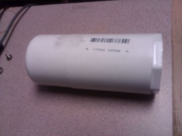
Nothing special. I picked 1-1/4" because I had some from a failed SNAP build earlier. It could be 1" or 1-1/2".
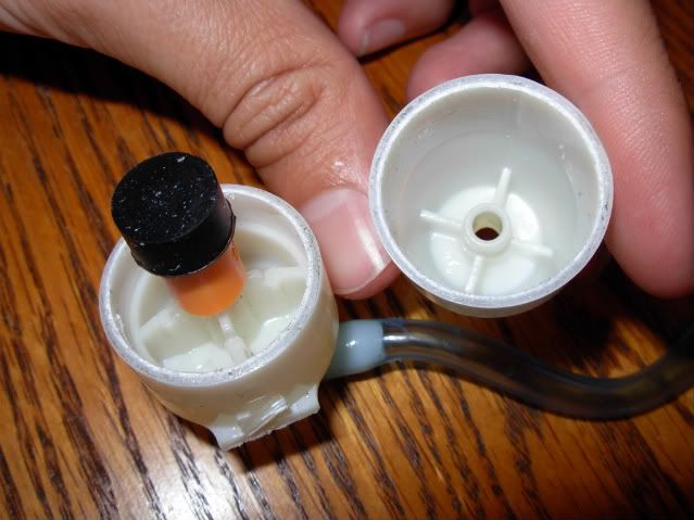
Here's the face of it:
It's a 1/2" to 1-1/4" bushing, but I can't find ones that nest inside the 1-1/4" pipe, so this will go in the coupler you see above. There's a steel fender washer epoxied to the back of the bushing for strength, a rubber fender washer for seal, and a ring of e-putty to (hopefully) keep the air from trying to leak through any gaps in the bushing-to-steel-washer bond.
You can see the steel washer and epoxy from the front:
===
The piston is where the 'magic' is. I'll be honest - until just a few days ago, I didn't bother to try to 'get' BPVs. They just felt like they were too complicated and prone to failed NerfSmithing rolls for me to try.
Of course, everyone knows someone who finally understands a technology and tries to implement it with their own technology w/o first understanding the existing body of knowledge.
Today, I shall be that idiot.
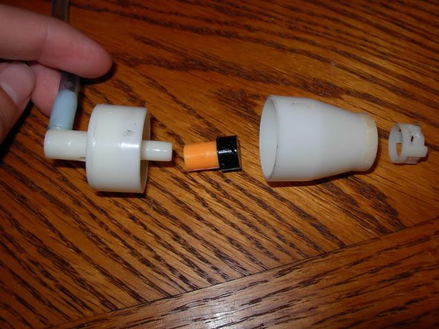
===
It's a 1/2" 000 rubber stopper crammed into a tube of 7/16" brass, with some epoxy to hopefully hold it in place. The way I see it, there won't be a lot of stress on this piece - on the intake, air will go up against it and around it, so it won't be under pressure. On the discharge, it will be pushed further back into the piston, so it won't be going anyplace.
There's a busted bicycle spoke screwed into a hole I made in the front of the stopper. The hole doesn't go all the way through - just deep enough for the threaded portion of the bike spoke. The smooth part is about 1" long. It will hopefully keep the piston face in alignment with the valve opening.
===
Here's the back of the piston.
The inner tube is 11/32" brass, force-fitted into a stub of 3/8" OD x 1/4" ID tubing. This will serve as an anchoring point for the rest of the pneumatics, but that's all TBD because I still need to drill out the PVC endcap.
Those are 2 AR springs from a Mav. One has been deliberately horked so they won't slide into the 7/16" tube.
===
That's it for now. The brass hasn't been cut yet because I don't have good measurements for inside of the tank. Again, need to hole out the endcap first.
I'll go into the pneumatics and frame as I build them - no point in saying what I'm going to do and then change my mind.