- Must fire standard streamline nerf darts
- Shoot 10 rounds in 10 seconds.
- Hit the back of a car from 80 feet
These goals were intentionally vague so that we the objectives could be approached from many angles. For instance you could shoot 10 darts at once to meet the ROF goal, etc
The actual contest kind of fell through but myself and one other guy continued building. This is my result and he should be finishing his soon and I’m sure he’ll stick it up here as well.
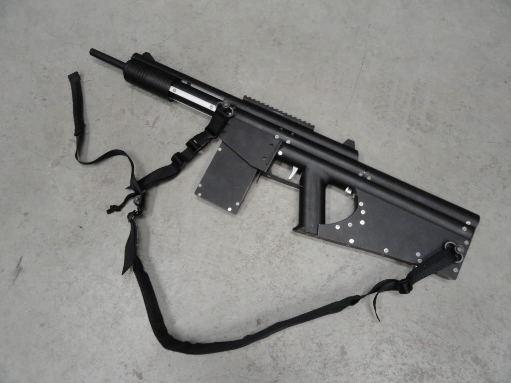
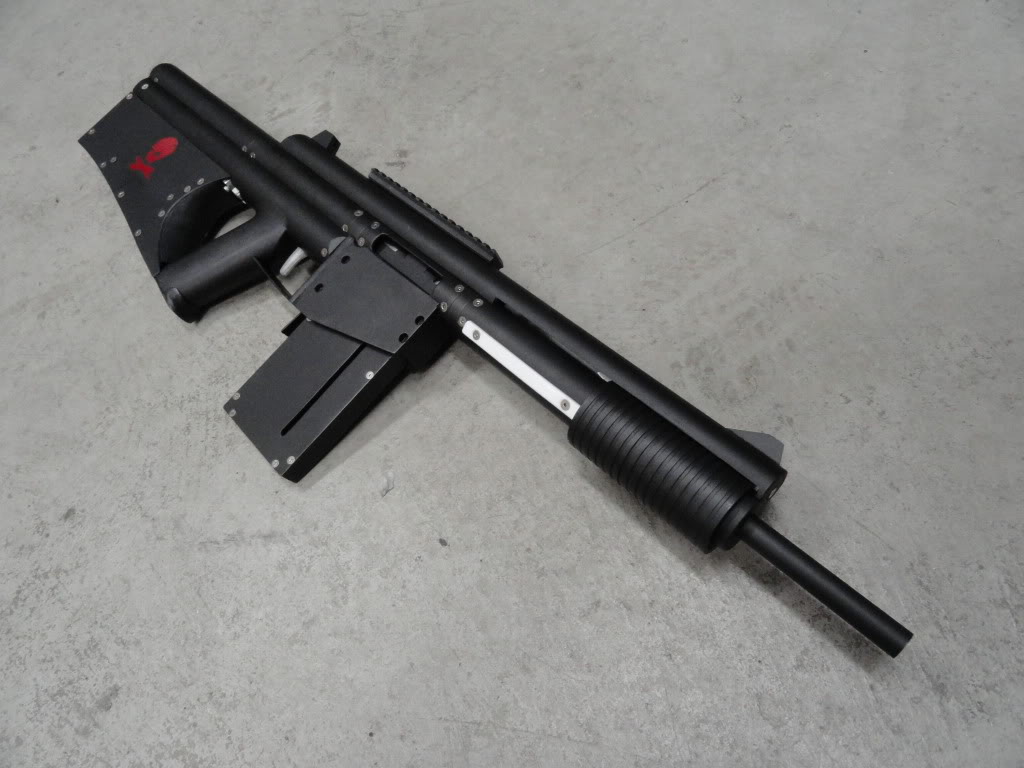
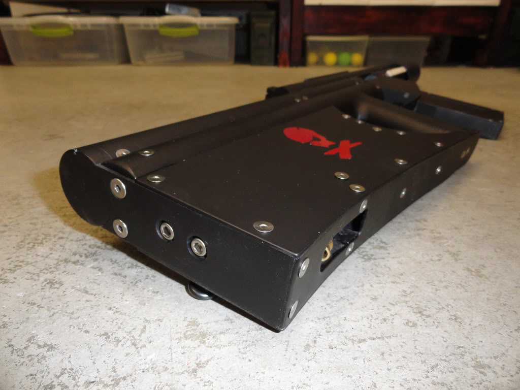
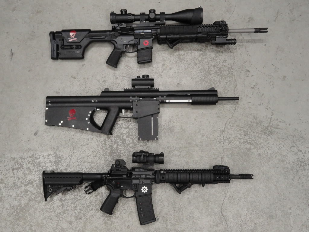
This rifle is the 12th gun I have made, hence BS-12, and I am dubbing it the Advanced Tactical Rifle, or ATR. It’s essentially the same type of rifle as the BS-8 with improvements in design, materials and the addition of semi-automatic cycling.
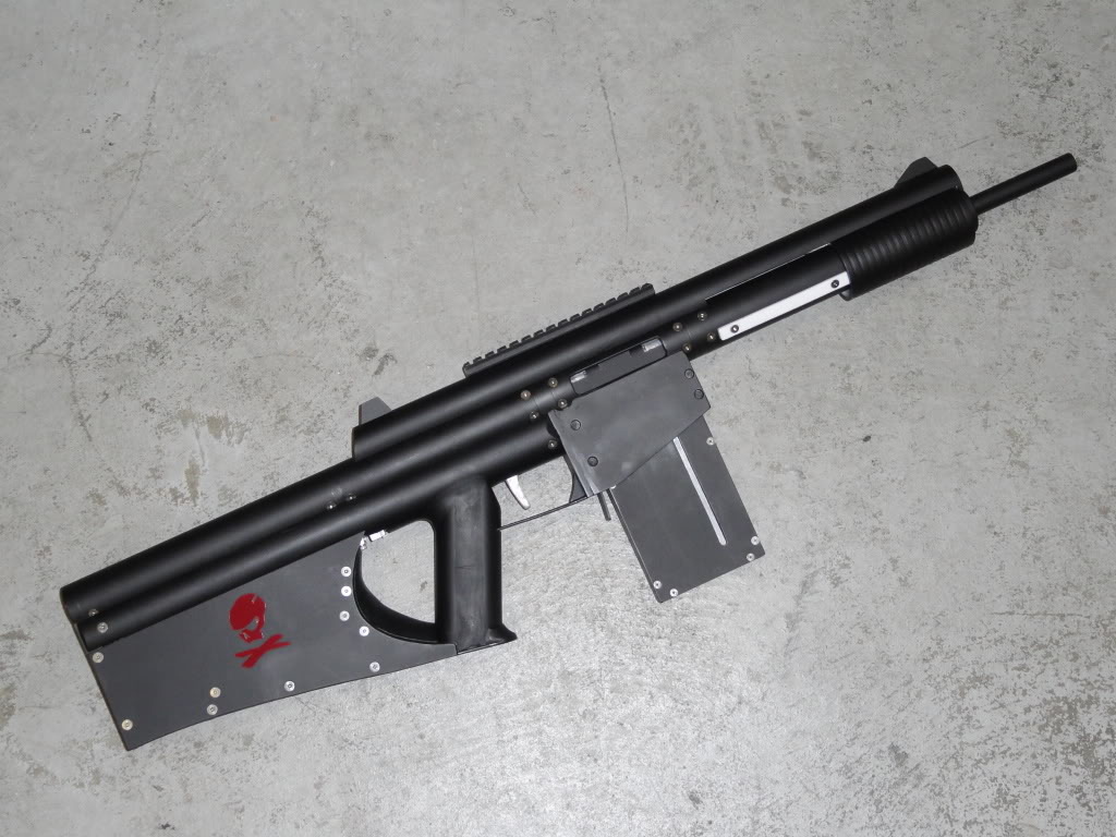
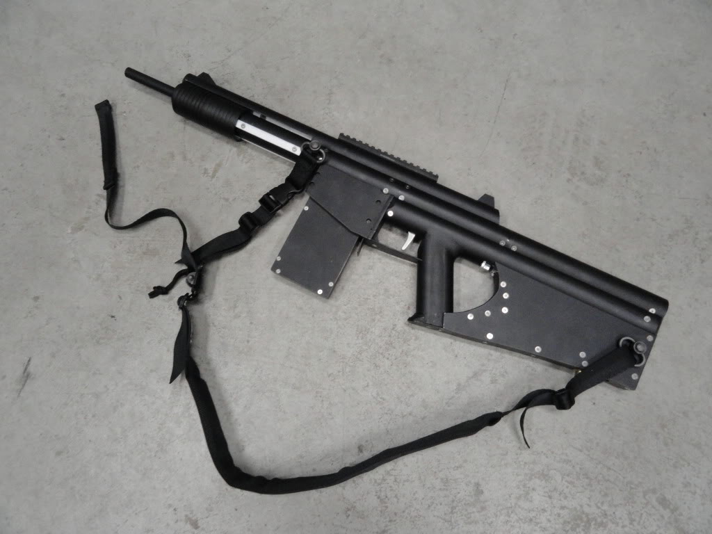
From the start I intended to make this rifle semi-automatic capable. I say capable because I never intended for it to be solely automatic. My vision was for a pump-action rifle with a semi-automatic mode available. Since the semi-automatic action would run off of compressed gas of some sort, I didn’t want it to be solely dependent on an energy supply that may run out, so I wanted it to be manually operable as well. I also wanted this rifle to be much more durable. This meant utilizing tougher materials than PVC and polycarbonate. While I still used both of those materials, the bulk of the rifle is aluminum 6061. Being able to machine the parts to very tight tolerances also lead to better seals which made it perform better and also enabled the auto-cocking function.
The whole thing is screwed together and with most of them being countersunk. There are over 120 fasteners in the whole rifle. Only a few parts are bonded together…mainly the pistol grip.
It fires streamline clip-system standard nerf darts WITHOUT shells making this rifle much much more practical to use.
What resulted is a detachable magazine-fed, pump-action, spring-plunger rifle which is auto-loading when attached to an external gas supply.
Specs:
Caliber 0.5 in
Plunger Volume 4.91 in3
Plunger Stroke 4 in
Muzzle Velocity 190 ft/s
Overall Length 33 in
Magazine Capacity 12
Rate of Fire
Pump-Action 80 RPM
Semi-Automatic 120 RPM
Range 165 ft
Barrel Length 12 in
Propulsion Hybrid Impulse/Acceleration
Magazine Detachable Bottom Feed
Using a standard chronograph I was able to clock the muzzle velocity. The max I have seen has been 194ft/s but it varies based on the dart. The lowest I have seen is around 170ft/s. In comparison any stock nerf gun will shoot at 45-50 ft/s. Standard mods will get them to around 60ft/s.
BALLISTICS
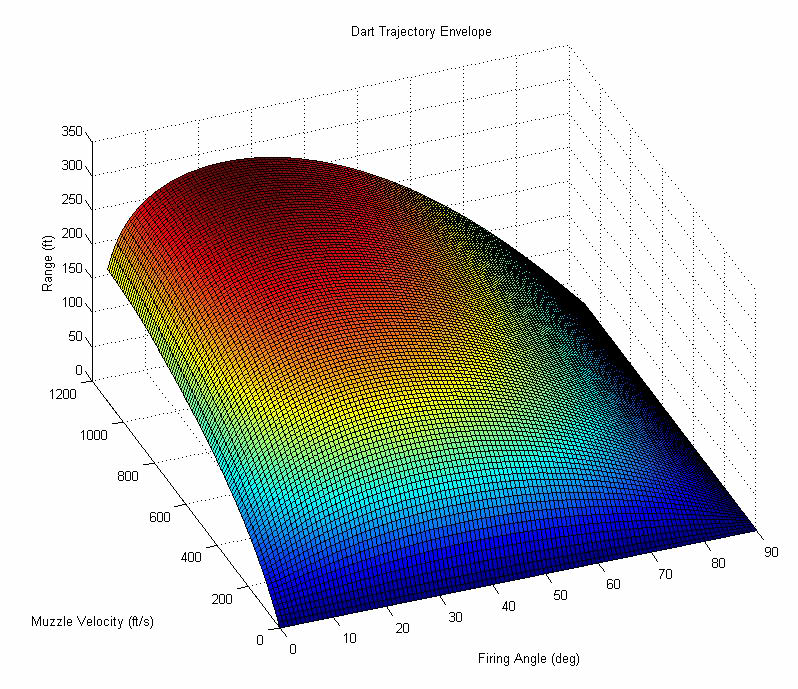
During the design of this rifle, I decided to write some programs to simulate the firing of a dart. By doing this and knowing the muzzle velocity of the gun, I can accurately predict the range. In order to compute the drag on the dart from the air I did a combination of simple computational fluid dynamics (CFD) models and empirical tests. I found a good value for the drag coefficient of a streamline dart. Knowing this value the subsonic drag can be computed and ultimately the trajectory. At transonic speeds the drag increases greatly due to shock wave formation. To account for this I applied an exponential increase in the drag from 0.8 Mach up to 1.0 Mach. I did not bother to go above Mach 1.0 for numerous reasons. For one….let’s be serious…no one is firing a nerf dart at the speed of sound. Two…I doubt a nerf dart would survive that velocity. Three….it is impossible for a spring-plunger type gun to even fire a dart above Mach 1.0.
Anyways, the figure below shows the full range envelope for a streamline dart. From 0-90 degrees firing angle and 0-1100 ft/s muzzle velocity.
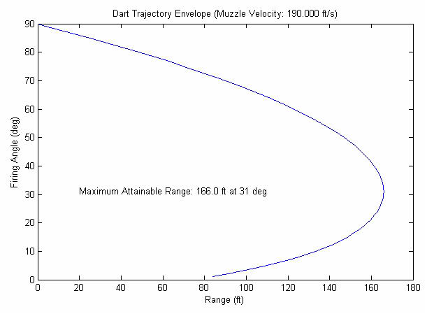
Knowing the muzzle velocity is 190ft/s for the ATR, the range vs firing angle can be plotted to determine the optimal firing angle.
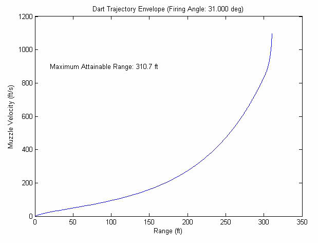
For completion, the plot of range vs muzzle velocity can be made as well. Notice the knuckle in the curve near the end as the transonic wave drag kicks in.
Finally, the actual dart trajectory can be plotted.
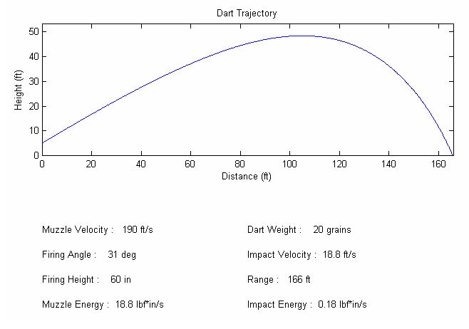
Maximum attainable range for the ATR is 166 feet. This calculated value correlates well with actual shot data.
On a side note, notice the maximum range from the full envelope of just over 300ft. It is physically impossible to fire a stock nerf dart any farther than that.
These scripts were written in MatLab and I am thinking about porting them to Java to make an interactive applet.
TECHNICAL
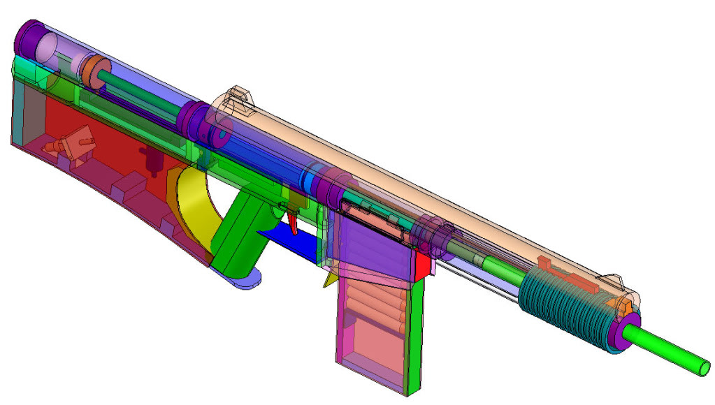
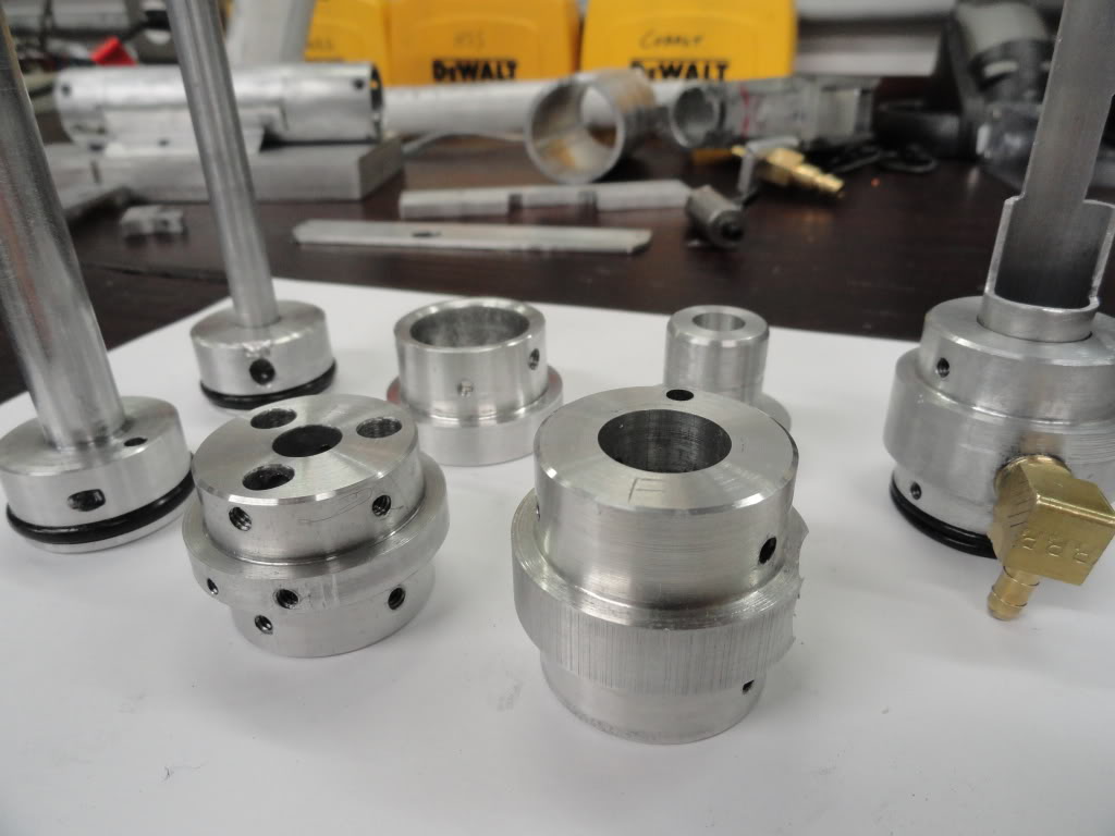
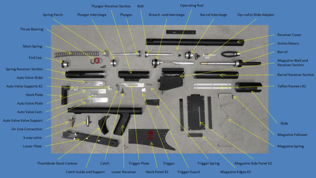
As is typical, this project started with a solid model to layout the major components and determine the primary dimensions. The main portion of the rifle consists of sections of 1.5” OD aluminum 6061 tubing with a wall thickness of 0.125”. The sections are connected together with what I call “interstages”. These are machined from 1.5” 6061 stock. There are four major sections that make up the rifle. Starting from the aft: Main Spring and Auto-valve, Plunger, Bolt/Breach, and Barrel. There are respective interstages between theses four sections.
BARREL
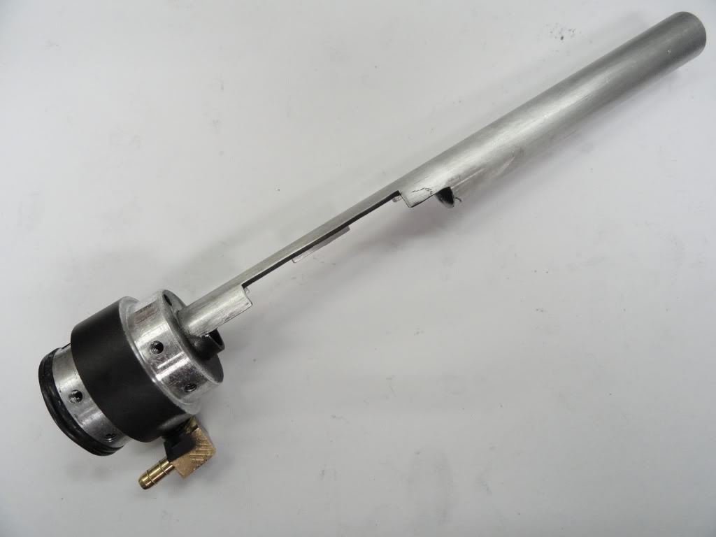
The barrel is 6061 aluminum tubing with an inner diameter of 0.53” and a wall thickness of 0.04”. This ID is perfect for near-frictionless acceleration of a streamline dart with a nominal diameter of 0.5”. A 4” section of 17/32” brass was turned down slightly to fit into the aluminum barrel at the breach end and acts as a constriction for an initial impulse to the dart.
PLUNGER
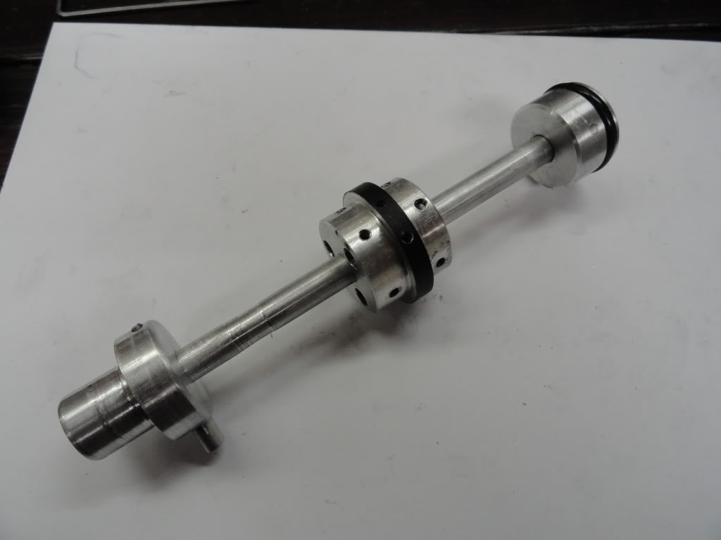
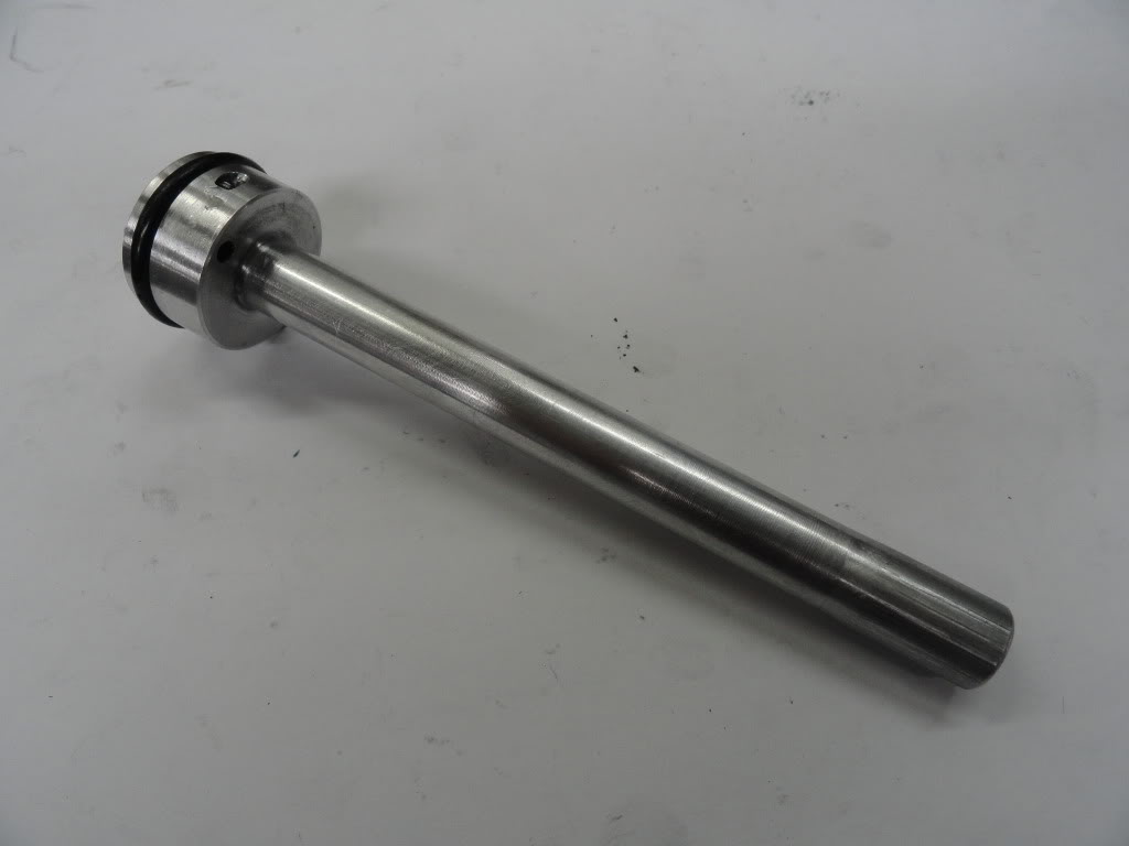
The plunger is pretty standard. The plunger head is machined from 1.25” 6061 stock and has an O-ring around it for sealing. The plunger shaft is 0.375” aluminum bar stock. The shaft goes through the plunger head and a steel pin goes through both to secure them together.
The main spring is a McMaster 9637K21 with a constant of 146.3. The length used in the rifle is a 11” so the resulting stiffness is 3.75 lbs/in, giving a full draw compression of 33 lbs. The spring interfaces the plunger through a perch attached to the back of the plunger shaft. The perch also mounts the auto-valve activating pin.
BOLT
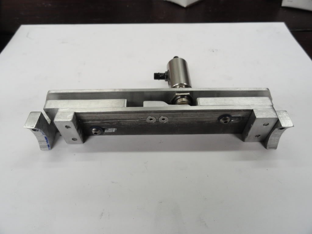
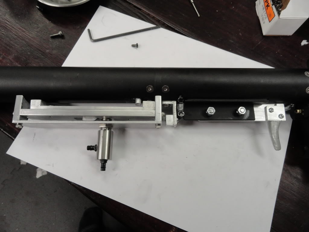
The bolt is unique to this design. It is machined from a solid piece of 1.25” 6061 stock and the forward end of the bolt matches the ID of the barrel. So a near perfect seal is made here without the use of an O-ring. About 0.75” back from the forward end of the bolt, the diameter necks down slightly to reduce friction when cycling. The aft end of the bolt forms a plunger head looking area with another O-ring. This head is what pushes the plunger back when the action is cycled. The O-ring is needed here because the chamber forward of the bolt head is where pressure is built to cycle the action in automatic mode. Corresponding O-rings are also found at the aft end of the barrel, where the bolt enters the barrel, and in the through holes for the operating rod above the barrel. A notch is cut in the front of the bolt at the bottom to let air in between the bolt and into the plunger cavity as the action cycles forward and the plunger cavity is opened up.
The operating rod rides in through holes in the interstages above the barrel and connects to the bolt head. An adapter connects to the operating rod at the forward end and either connects it directly to the pump handle or connects it to the action spring, which is a section of surgical tubing. Surgical tubing offered the right amount of stiffness and stretch.
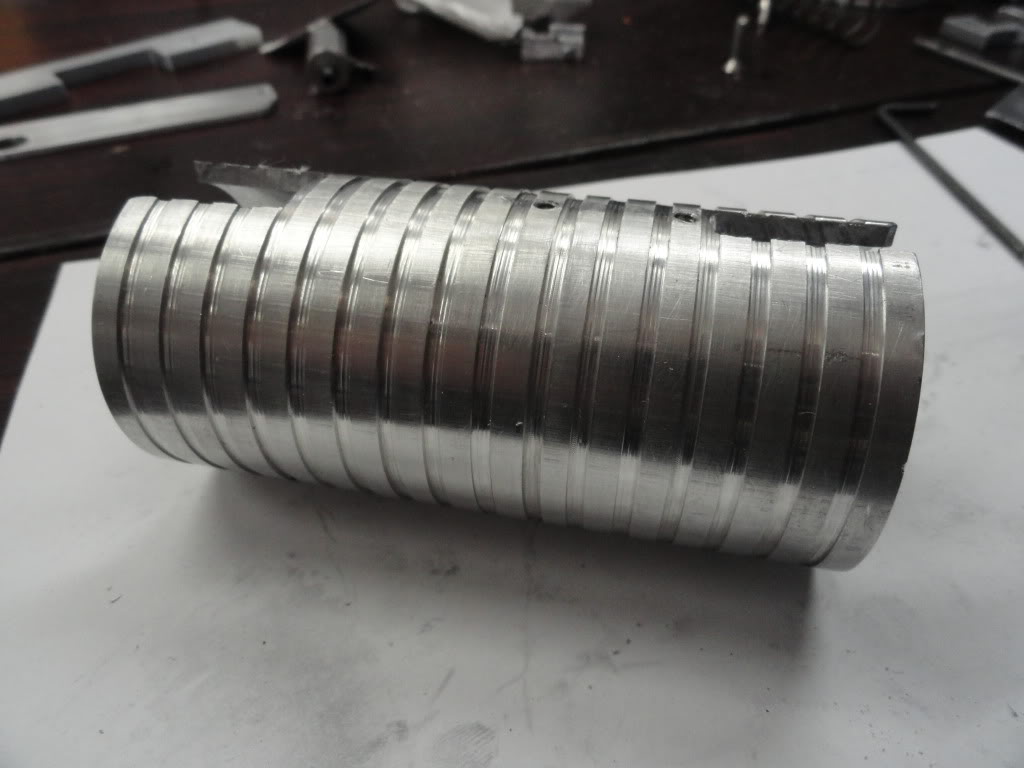
The pump handle is a section of 2” 6061 tubing. I turned some slots into it to offer some positive grip and it works quite well. TO keep the pump handle from sliding on the receiver and scuffing the paint it rides on two Teflon runners attached to the fore-end.
MAGAZINE
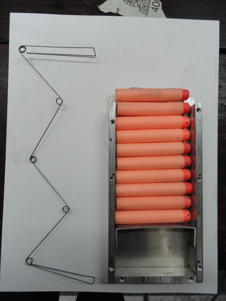
The magazine is similar to the Nerf clip system mag except it is built up with aluminum. The spring is bent from 0.03” music wire
FIRE CONTROL
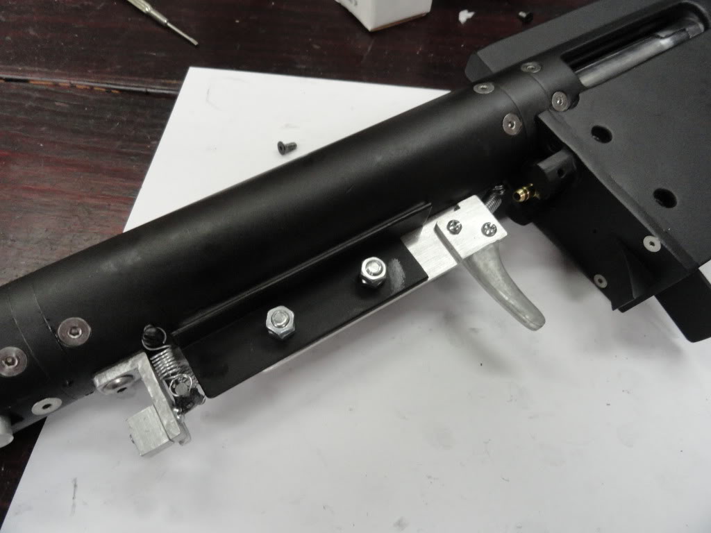
The trigger is pretty standard. It consists of an aluminum plate with a ramp at the aft end. The catch is made from 0.125” steel rod and is welded together for strength.
Edited by CaptainSlug, 20 November 2018 - 02:26 PM.


