Jump to content


Photo

Semi Auto Valve For Backfire Tanks


19 replies to this topic

#1 shmmee

shmmee

    Member

  • Members
  • 467 posts

Posted 15 January 2011 - 08:56 PM

Homemade Semi Auto Valve for Backfire backpressure tanks.

This valve is inspired and builds upon frame work done by Cheesypiza001, and Boot. They modified a hornet sliding valve to fire a backfire tank in semi auto fashion.

Cheesypiza001's semi auto valve Concept; semi-auto'd a firefly.
Mirage-ss by boot Semi-auto rscb

Both systems were successful in filling a tank, and venting the tank without venting the main reservoir. This just provides a little more polish with some unexpected benefits. This was developed to compliment my hornet tank expansion mod, but should work for any backfire backpressure tank.

Issues resolved: Hornet sliding valves have more inputs than are needed for one tank, and sliding the O-rings past any of the extras will vent your reservoir. Those extra inputs are also waiting to chew up your o-rings.
Benefits: O-rings only traverse one hole. Extra brass on the venting end will turn your valve into a piston that will push back on a trigger (as discovered by Boot), or maybe open a bolt sled (a hint at what I've been working on). It looks simpler and cleaner, and unless something breaks, a seal fails, or you push your piston through the cross section, you can't vent your reservoir.

Materials:
Hornet plunger rod (or figure out how to make your own)
13/32 brass tube
Solder, flux (or solder with a rosin core), and heat source (like a torch)
zip ties
lubricant
tubing

Tools:
pipe cutter
drill or drill press
torch (propane, benzine, acetylene, something to make the pipe hot. A candle might even work...)
sharp pointy knife to help with de-burring
Dremel with cut off wheel and 3/8” ish sanding or grinding drum (the closest to your brass tube diameter that you have)
drill bits: 9/64” (or 1/8” if you don't have the 9/64") and 3/8” (to de-burr after the 9/64” hole is drilled)
needle nosed pliers

helpful:
Heat gun (to soften tubing and stretch over brass tube.)
Vise

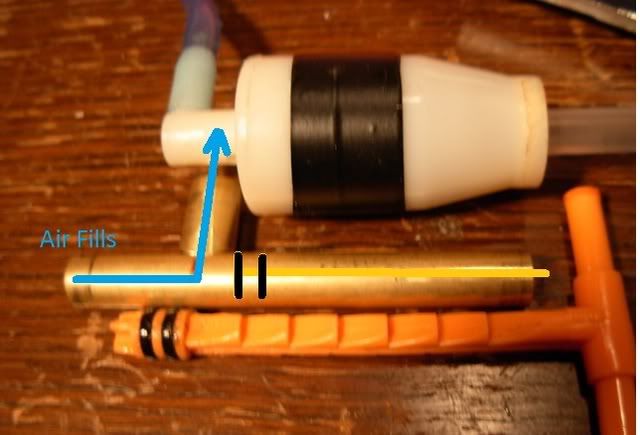
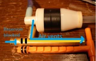
Theory and concept: A brass tee is made. The middle leg is hooked up to the tank, one leg is hooked to the air reservoir, the piston is inserted into the third leg. When both o-rings on the piston are behind the tee, air flows from reservoir to tank. The piston is depressed and when both o-rings straddle the middle leg of the tee, all 3 passages are isolated from each other. When both o-rings pass the middle leg, the tank vents around the piston post and out to atmosphere, causing the tank to fire (without venting the reservoir). Pressure is maintained on the piston in all stages causing the piston to return to the priming state as soon as no counter pressure exists. Testing at 40 psi results in a slightly firm, but manageable trigger pull.
Posted Image

Posted Image

Construction:
Build this:
Posted Image

Take your brass tube, and chop off a 1/2” long piece. You'll need this for a guide. Now grab your Dremel and grinding drum and grind a saddle (U shaped divot) into the tip on both top and bottom sides.
Posted Image
Fit check with the 1/2” long piece. You want metal to keep constant contact between both parts when one straddles the other. Squishing the tall tips together slightly may help fit up. Once free of gaps, chop off about 3/4” of the ground down side. This will become the middle leg of the tee.

Now figure out how long you want the top part of the tee by laying the hornet piston next to it. You want to give your self enough space for both sets of o-rings to pass by the middle leg. Mark that spot. Don't drill your vent hole till after you have solder in place. I'm not going to be too specific on dimensions, you can figure out that stuff, and tailor it to your own needs.

Solder time. “Tin” your pieces by getting solder on the parts to be joined before you try to join them, Apply flux to both contact points of the brass tee (the saddle inside and out) and the cross section where the tee will be mounted. Now heat and melt solder to both of those areas. Apply heat to the tube not solder. Heat the tube, remove the heat, and apply the solder. Fine wire solder will be easier to work with than a thicker gauge solder. Get globs of solder built up on the saddle of the middle leg.
Posted Image

Now that we have solder built up on the cross section, drill the vent hole (9/64”) in the center of where the tee will be placed. File off the solder around the vent hole (leaving it around where the tee will be placed. We don't want solder getting inside. Use the 3/8” drill bit to hand ream out the debris from your 9/64” hole.
Posted Image

To join the pieces, just place the tee on the cross section and heat them both. They'll bond. Quick and easy. The better prep and fit up, the easier this last step will be. Once cool, air test by plugging both holes on the cross brace with fingers and sucking on the middle leg.


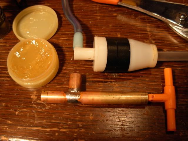
Lube your hornet piston and stuff it in. I found the lube shown in the first picture in the faucet guts section of the hardware store. It was labeled "safe for all gaskets including ceramic" and "non-toxic" (so no petroleum distillates) It lubes well. It's also thick and stays where you put it.

Plumb by warming 3/8” tubing and stretch with a pair of needle nose pliers, then slide them over their connection. Or goop barbed connections in place as needed. Secure them with a zip tie.
Here it is being integrated into my latest project.
Posted Image

Edited by shmmee, 17 January 2011 - 01:35 PM.

  • 0
"and we should respect the people who make our blasters. Even if we do molest the hell out of them..."
~BritNerfMogul


#2 iDrag0m1r

iDrag0m1r

    Member

  • Members
  • 66 posts

Posted 15 January 2011 - 09:24 PM

Damn it! I just got a hornet this morning, and stopped at Ace too! Why couldn't you have posted this earlier? Just joking! Great work!
  • 0
I AM JUNIOR!

#3 Boot

Boot

    Member

  • Members
  • 90 posts

Posted 15 January 2011 - 09:39 PM

Nice! I have actually made several variations of my original valve (and am saving them for the final "Mirage" post). Although this seems like a difficult build, the results are awesome. My only fear is that the solder might not hold out, but I have absolutely no experience in that, so I'm just guessing.

That last picture looks interesting though! It seems very similar to what I'm working on, except from what I can tell the "trigger" pull will be very long, perhaps requiring two handed operation. Regardless, awesome work. I am very interested in seeing where this goes, and how you're project compares to the Mirage 2.0!

PS: brass really seems like a "magic" material! I'm going to have to get my hands on some.
  • 0
QUOTE
If you try to shoot over 45 feet with a magstrike accurately you fail

I beg to differ

#4 arfink

arfink

    Member

  • Members
  • 246 posts

Posted 15 January 2011 - 10:17 PM

Now, many people on IRC, including obob, tried to convince me that such a setup will make the trigger pull obscenely hard. Let me know how that works out for you, because if it does I'm going to keep my newly built shuttle valve for something that needs it and move back to a syringe valve for my original design.
  • 0
A2GS + 4 meg RAM + 128 meg CF + 9600 Baud Lantronix = WIN

#5 jubjub517

jubjub517

    Member

  • Members
  • 174 posts

Posted 15 January 2011 - 11:17 PM

Issues resolved: Hornet sliding valves have more inputs than are needed for one tank, and sliding the O-rings past any of the extras will vent your reservoir. Those extra inputs are also waiting to chew up your o-rings.
Benefits: O-rings only traverse one hole. Extra brass on the venting end will turn your valve into a piston that will push back on a trigger (as discovered by Boot), or maybe open a bolt sled (a hint at what I've been working on). It looks simpler and cleaner, and unless something breaks, a seal fails, or you push your piston through the cross section, you can't vent your reservoir.


I hate to say this, but I'm going to have to protest this.

In your current setup, your fighting against the pressure of the reserve tank. In cheesy's mod, he had o rings on both sides of the reservoir's input. This is the same basic concept zero invented. This eliminates all the pressure against the trigger. Although you say it's manageable, it can be a hell of a lot better.

The extra inputs on a hornet valve don't hurt the o rings in any way. In fact, the sharp thin edge of the brass is more likely to damage your o rings then the hornet. This doesn't vent your reservoir either, which is why there are two o rings instead of just one.

If you really want a "semi-auto valve", I'd suggest just using a hornet trigger valve. If you are unable to get your hands on one, then I suggest atomatron's valve. Using cpvc is a hell of a lot easier then dremeling and soldering brass. But thats just my 2 cents.
  • 0
[18:17] <+Jugs> Hey beefy
[18:17] <+Nerfer> pls dont call me that
[18:18] * Nerfer is now known as Guest17574
[18:18] <+Lucian151> Woah its Beefy Theify
[18:19] <+Guest17574> STOP CALLING ME THAT IM NOT FAT
[18:19] <+Guest17574> pls

#6 shmmee

shmmee

    Member

  • Members
  • 467 posts

Posted 15 January 2011 - 11:25 PM

Now, many people on IRC, including obob, tried to convince me that such a setup will make the trigger pull obscenely hard. Let me know how that works out for you, because if it does I'm going to keep my newly built shuttle valve for something that needs it and move back to a syringe valve for my original design.


Nope, at 40 psi the trigger pull is firm, but extremely manageable. (tested from an air compressor, a constant and regulated source)

Edited by shmmee, 16 January 2011 - 11:02 AM.

  • 0
"and we should respect the people who make our blasters. Even if we do molest the hell out of them..."
~BritNerfMogul


#7 arfink

arfink

    Member

  • Members
  • 246 posts

Posted 15 January 2011 - 11:29 PM

Then to heck with the naysayers, I'm going back to my syringe valve. It's got an even smaller piston head than yours does, so it'll be even easier to pull.

Edited by arfink, 15 January 2011 - 11:31 PM.

  • 0
A2GS + 4 meg RAM + 128 meg CF + 9600 Baud Lantronix = WIN

#8 shmmee

shmmee

    Member

  • Members
  • 467 posts

Posted 15 January 2011 - 11:33 PM

Nice! I have actually made several variations of my original valve (and am saving them for the final "Mirage" post). Although this seems like a difficult build, the results are awesome. My only fear is that the solder might not hold out, but I have absolutely no experience in that, so I'm just guessing.

That last picture looks interesting though! It seems very similar to what I'm working on, except from what I can tell the "trigger" pull will be very long, perhaps requiring two handed operation. Regardless, awesome work. I am very interested in seeing where this goes, and how you're project compares to the Mirage 2.0!

The trigger pull doesn't have to be any longer than a standard hornet trigger valve pull, i'm just exploiting a longer trigger pull to assist with the project it's going into. Looking forward to mirage 3.0! I'll pm you some details when i get a moment.
  • 0
"and we should respect the people who make our blasters. Even if we do molest the hell out of them..."
~BritNerfMogul


#9 shmmee

shmmee

    Member

  • Members
  • 467 posts

Posted 16 January 2011 - 12:03 AM

Issues resolved: Hornet sliding valves have more inputs than are needed for one tank, and sliding the O-rings past any of the extras will vent your reservoir. Those extra inputs are also waiting to chew up your o-rings.
Benefits: O-rings only traverse one hole. Extra brass on the venting end will turn your valve into a piston that will push back on a trigger (as discovered by Boot), or maybe open a bolt sled (a hint at what I've been working on). It looks simpler and cleaner, and unless something breaks, a seal fails, or you push your piston through the cross section, you can't vent your reservoir.


I hate to say this, but I'm going to have to protest this.

In your current setup, your fighting against the pressure of the reserve tank. In cheesy's mod, he had o rings on both sides of the reservoir's input. This is the same basic concept zero invented. This eliminates all the pressure against the trigger. Although you say it's manageable, it can be a hell of a lot better.

The extra inputs on a hornet valve don't hurt the o rings in any way. In fact, the sharp thin edge of the brass is more likely to damage your o rings then the hornet. This doesn't vent your reservoir either, which is why there are two o rings instead of just one.

If you really want a "semi-auto valve", I'd suggest just using a hornet trigger valve. If you are unable to get your hands on one, then I suggest atomatron's valve. Using cpvc is a hell of a lot easier then dremeling and soldering brass. But thats just my 2 cents.

I really do appreciate input. Good, bad, or indifferent, Though thanks for being civil in your disagreement. I would probably be more concerned about a heavy trigger pull if i wasn't relying on it to open a breach for me. If it's still more force than i need, i can counter balance with a spring. I haven't weighed it, but I'd guesstimate about 6-8 pounds of trigger pull. I'll see how the o-rings hold up over time and use. I'll also take a look at atomatron's valve. Thanks for the new things to look at.

Did some math (which has been wrong before) With a 3/8" diameter (.1875" radius) piston having a surface area (Pi*r squared) of .11039"*40 psi=4.415 pounds of pull on the trigger. (Just Some Bob, feel free to check and correct me if I'm wrong...again...). Four and a half pounds? I'd call that manageable.

Edited by shmmee, 16 January 2011 - 01:34 PM.

  • 0
"and we should respect the people who make our blasters. Even if we do molest the hell out of them..."
~BritNerfMogul


#10 Boot

Boot

    Member

  • Members
  • 90 posts

Posted 16 January 2011 - 03:20 AM

The trigger pull doesn't have to be any longer than a standard hornet trigger valve pull, i'm just exploiting a longer trigger pull to assist with the project it's going into. Looking forward to mirage 3.0! I'll pm you some details when i get a moment.


Oh I know, just from the last picture (and you're latest posts) it looks like you're actuating a breech with the valve. The direct connection that you seem to have means that you will have a trigger pull as long as whatever dart you are using. (I have a similar setup in the Mirage 2.0, but with a minor change to address this problem as, since I generally use streamlines I would have a ridiculous 3" trigger pull otherwise). It looks awesome though. I also like the use of expanded hornet tanks. i never had the confidence to open air tanks since they are so hard to get here, and so took the lazy (and less effective) way of using BS tanks.
  • 0
QUOTE
If you try to shoot over 45 feet with a magstrike accurately you fail

I beg to differ

#11 shmmee

shmmee

    Member

  • Members
  • 467 posts

Posted 16 January 2011 - 09:24 AM

The trigger pull doesn't have to be any longer than a standard hornet trigger valve pull, i'm just exploiting a longer trigger pull to assist with the project it's going into. Looking forward to mirage 3.0! I'll pm you some details when i get a moment.


Oh I know, just from the last picture (and you're latest posts) it looks like you're actuating a breech with the valve. The direct connection that you seem to have means that you will have a trigger pull as long as whatever dart you are using. (I have a similar setup in the Mirage 2.0, but with a minor change to address this problem as, since I generally use streamlines I would have a ridiculous 3" trigger pull otherwise). It looks awesome though. I also like the use of expanded hornet tanks. i never had the confidence to open air tanks since they are so hard to get here, and so took the lazy (and less effective) way of using BS tanks.

Yup. Boot wins the cookie. I'm trying for a clip fed semi-auto. (which has been done before, but I haven't seen any without extensive machining. I'm trying for something simple enough that a modder with moderate experience can duplicate.) With .75" steffans and extra .25" to seal the breech it will have a long trigger pull. I definitely wouldn't call using a BS tank lazy, or less effective. They were designed with the capacity to fire arrows, and probably have a faster output too. The barrel side holes in a hornet tank are tiny. It's probably what I'd be using if i had any.

Edited by shmmee, 16 January 2011 - 11:08 AM.

  • 0
"and we should respect the people who make our blasters. Even if we do molest the hell out of them..."
~BritNerfMogul


#12 shmmee

shmmee

    Member

  • Members
  • 467 posts

Posted 16 January 2011 - 03:13 PM

I'm trying for a clip fed semi-auto. (which has been done before, but I haven't seen any without extensive machining. I'm trying for something simple enough that a modder with moderate experience can duplicate.) With .75" steffans and extra .25" to seal the breech it will have a long trigger pull.


At our wars, any dart that doesn't have a full inch of foam gets ignored.
There has to be a limit somewhere, or eventually you're just shooting BBs with a foam 'beard' glued on.

I predict you're going to want to use leverage to shorten that trigger pull.
At which point the issue of fighting chamber pressure will get multiplied.


Oh. That's really, really good to know. I had originally planned on using a lever, but It is going in a raider shell, which doesn't have much room for levers and such. Guess it's about time for a small set back. I appreciate the heads up.
  • 0
"and we should respect the people who make our blasters. Even if we do molest the hell out of them..."
~BritNerfMogul


#13 Draconis

Draconis

    I am not Lord Draconical

  • Members
  • 2,712 posts

Posted 17 January 2011 - 02:06 AM

In your current setup, your fighting against the pressure of the reserve tank. In cheesy's mod, he had o rings on both sides of the reservoir's input. This is the same basic concept zero invented. This eliminates all the pressure against the trigger. Although you say it's manageable, it can be a hell of a lot better.


Grouchy much, Jubs? Zero's valve is somewhat different, and he didn't really invent it, anyway. He simply attempted to design a valve which he could make from commonly available parts. Schmee obviously has some soldering skills, but that doesn't mean that they are exotic. It just takes a little practice. This valve design is actually very much like that of the Triple Strike or the Big Salvo.

Then to heck with the naysayers, I'm going back to my syringe valve. It's got an even smaller piston head than yours does, so it'll be even easier to pull.


Really? That's too bad, because I thought it was a great idea. Sorry some of the others are giving you guff.
  • 0
[15:51] <+Noodle> titties
[15:51] <+Rhadamanthys> titties
[15:51] <+jakejagan> titties
[15:51] <+Lucian> boobs
[15:51] <+Gears> titties
[15:51] <@Draconis> Titties.
[15:52] <+Noodle> why is this so hard?

#14 shmmee

shmmee

    Member

  • Members
  • 467 posts

Posted 17 January 2011 - 09:37 AM

Really? That's too bad, because I thought it was a great idea. Sorry some of the others are giving you guff.

That's ok, i've gotten a lot of feedback on this valve, positive, negitive, but all of it helpfull. Just some bob really helped me avoid a lot of wasted work (this valve supports a gun I'm designing to be used at BAFF. It's a long drive from Utah to California, and it really would of sucked to have the gun spot banned because the darts were too short.)

Draconius was also able to point me to an old post that I didn't know existed, and could be usefull.

I do feel justified after calculating the trigger pull to be about 4.5 pounds @40 psi. Any valve with a 0 pound pull would have to have a return spring, and a larger diameter piston would have more friction to overcome.

You're right though, soldering a joint isn't that exotic. It's also very strong. I've solldered plumbing in the basement before, and this project was much easier. This is the second valve i've built, and both are air tight. I feel my design remains competitive, and an ideal choice for a backfire backpressure tank. The short 2-3 hour build time also helps.

All things considered, thanks for the support!

Edited by shmmee, 17 January 2011 - 01:37 PM.

  • 0
"and we should respect the people who make our blasters. Even if we do molest the hell out of them..."
~BritNerfMogul


#15 archangel24

archangel24

    Member

  • Members
  • 215 posts

Posted 17 January 2011 - 11:07 AM

I like it, but if i may, technically they are called backpressure tanks and not backfire tanks.
  • 0
QUOTE(Talio @ Oct 14 2010, 10:37 PM) View Post

I would much perfer a game that's free of KY. I like it rough. Right, Vacc?

"She went all Ghetto Fab on you."

#16 Doom

Doom

    NH's Official In-House Physicist

  • Administrators
  • 559 posts

Posted 17 January 2011 - 11:58 AM

Interesting work.

It seems some people have independently reinvented the 3-way valve. As a note, these valves are sold as "directional control valves" (3-way refers to a variety of DCV). DCVs have been used in similar setups by spud gunners for over two years now. Here's an old thread of mine where I use one with a QEV (a manufactured "backpressure valve"): http://nerfhaven.com...showtopic=12468

I personally don't bother with any homemade valves at this point. They require too much work to get to work right in my experience. And 3-way valves are not necessarily expensive. You can find adequate ones for fairly cheap, and I'm confident that even if you value your time at only $5 an hour, you can find manufactured valves that are cheaper

Good luck with the clip-fed semi-auto too shmmee! That can be tricky to do. If you run into any problems, I may have had the same problem before, so feel free to email me.
  • 0

#17 Boot

Boot

    Member

  • Members
  • 90 posts

Posted 17 January 2011 - 07:15 PM

@Doom

That's interesting, actually i see these valves more as modifications. The valve in the Mirage-ss took about 3 minutes of hacking to get to work. I don't know about Shmmee's valve, but by using components that Hasbro has already designed to work reliability is not an issue (in general).
  • 0
QUOTE
If you try to shoot over 45 feet with a magstrike accurately you fail

I beg to differ

#18 knexpert66

knexpert66

    Member

  • Members
  • 133 posts

Posted 18 January 2011 - 08:14 AM

Nice! I love when people come up with amazing ideass like this. Great work!
  • 0
Please, call me Busted.

#19 Crom Strom

Crom Strom

    Member

  • Members
  • 33 posts

Posted 18 January 2011 - 10:16 AM

Using cpvc is a hell of a lot easier then dremeling and soldering brass. But thats just my 2 cents.


Soldering brass isn't too difficult. Hell, you should be able to pull it off with a propane torch (if you're willing to wait about one hundred million years for the damn brass to heat properly).

One suggestion for soldering brass, though: sand the areas you want to apply solder to, then only apply solder to one of the surfaces you want to join. It'll make the joint look a lot better and you'll get the same effect with fewer materials.
  • 0

#20 shmmee

shmmee

    Member

  • Members
  • 467 posts

Posted 18 January 2011 - 01:10 PM

Using cpvc is a hell of a lot easier then dremeling and soldering brass. But thats just my 2 cents.


Soldering brass isn't too difficult. Hell, you should be able to pull it off with a propane torch (if you're willing to wait about one hundred million years for the damn brass to heat properly).

One suggestion for soldering brass, though: sand the areas you want to apply solder to, then only apply solder to one of the surfaces you want to join. It'll make the joint look a lot better and you'll get the same effect with fewer materials.

Brass tubing is very thin, and heats very quickly. The propane tourch i used had it up to temp in a few seconds.
Solder likes to stick to more solder better than sticking to bare brass. "Tinning" both sides helps to avoid a lot of trouble with the final joining. Excess solder isn't too tragic of a waste either.
The first valve i made had a minimum ammount of solder prepaired on the middle leg. Each time i tried to apply more solder, I pushed the fitting around, knocked it off a couple of times and risked getting solder on the id of the long tube. (clamping it down probably would of helped.) It eventually sealed up, but took a couple of minutes. The final joining on the second valve i assembeled (the one with a noticable bead built up around the edge) was as simple as placing it on the pipe and heating the two pieces for a few seconds. The moment both pieces got up to temperature, The middle leg settled, solder joined, and it was a perfect air tight joint with 15-20 seconds of heat. Well worth the prep work.

I agree with you on sanding the brass prior to soldering though, i just forgot.

Edited by shmmee, 18 January 2011 - 01:12 PM.

  • 0
"and we should respect the people who make our blasters. Even if we do molest the hell out of them..."
~BritNerfMogul


0 user(s) are reading this topic

0 members, 0 guests, 0 anonymous users