
After building my first SNAP, I realized how much I was frustrated by all the fine tuning that was required for the catch system to work properly. I soon began brainstorming ideas for a possible new homemade design that would be simply, yet reliable. The design that I originally had thought of required the machining of wood, polycarb, and aluminum. I knew that this idea would not do, because it was too complex. I eventually had an “epiphany” one day, while building my second SNAP….I thought, “what if the groove in the center of a coupler was utilized as the ‘catch piece’?” I began to develop on that idea, and eventually came up with this. During the entire design process, the design evolved about 5-6 times in total, over the month and a half that it was stored in my mind.
It is because of the complications that the SNAP brought me, that I today present to the NIC, the Coupler Catch design. I have yet to deem an official name to this design/blaster.
I would first like to give credit to Modman, for his “old” “endcap catch” design. It is this design that gave me the placement of the catch spring and screw that is incorporated in the current model. Also, I do realize that this design is similar to that of the Rainbow. However, I had this idea well in my head before the Rainbow was release. The Rainbow design, did, however, give me some ideas/help in the design, so I thank Stark/Beaver for the design.
Goals
I had set many self-goals for this project/design prior to building. I wanted for the blaster to be simple, but reliable. I did not want for there to be too many pieces involved, and I wanted to machining of plastics or metals to be required. Also, I wanted for the blaster to be held together only by screws (excluding the bushing, obviously), to make quick/easy repairs and even field stripping possible. I meant for the design to meet with all of these goals, because if it didn’t, I would either have to “ditch” the design, or render it…why? Because I thought to myself, that if the design did not meet the goals (which were quite basic), then I would not be contributing anything to the community, and nobody would have the urge to build a replica, due to its negative traits.
Design
In the current design, a ½” PVC coupler is used to act as the “catch piece”, while a set of ¾” PVC endcaps are used to balance the plunger rod inside the coupler. There is a notch in the plunger rod that the groove of the coupler eventually rests in to, when the spring is compressed and the rod is pulled back.
Here is a diagram of the current design of the Coupler Catch:
I apologize for the crude MS Paint representation. I will make a clearer diagram if anyone asks for one.
As you (probably) can see, when unprimed, the plunger rod is naturally raising the coupler “catch piece” inside the plunger tube, due to its position in the two endcaps. As the plunger rod is pulled back (the front endcap acts as the spring rest), the groove in the coupler eventually falls into place in the notch in the plunger rod, due to a spring above it. The catch piece and catch spring are kept in balance by a #8-32 bolt that threads through the spring, and into the coupler.
The trigger assembly is a completely separate and somewhat complex system. It consists of an angle bracket, a weak “trigger spring”, and two #6-32 x ½” screws. The angle bracket , like in SGNerf’s “PVC Catch Ring” design, moves on a pivot, and it connected to a screw that is screwed into the plunger tube. The head of the screw rests nicely in the hole of the bracket. There is a weak spring between the plunger tube (1 1/4'” PVC) and the bracket (the section held in place by the screw). There is then another screw and a #8 washer (super glued to the head), which enters a hole drilled in the plunger tube, so that when it enters the plunger tube, it pushes the catch upwards, releasing it. The screw/washer piece is hot glued to the angle bracket. When you pull the front of the angle bracket backwards, the screw in the back of the bracket enters the plunger tube.
Here is a picture of the trigger assembly:
The more the merrier!
Here's a picture of one of the two endcaps that keeps the catch/plunger rod balanced/centered:
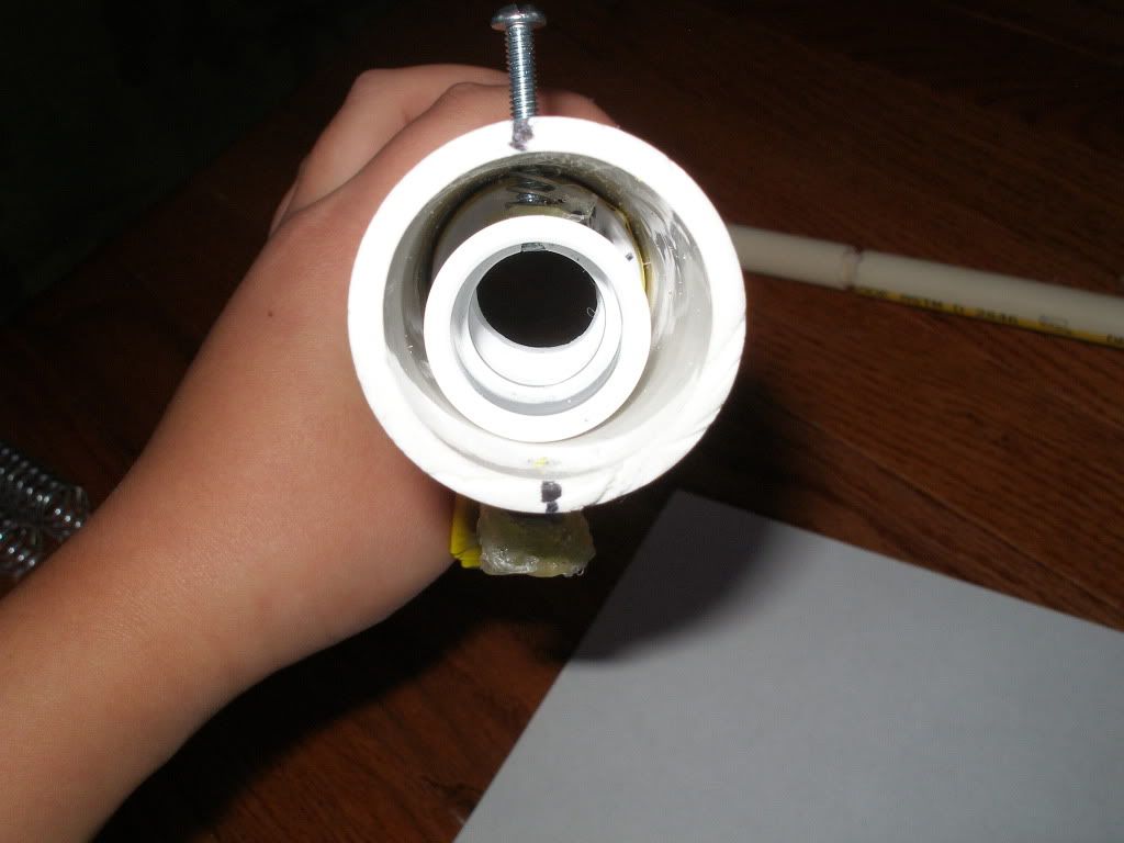
A look down the end of the plunger tube, from the back:
Here's a picture of my current plunger head:
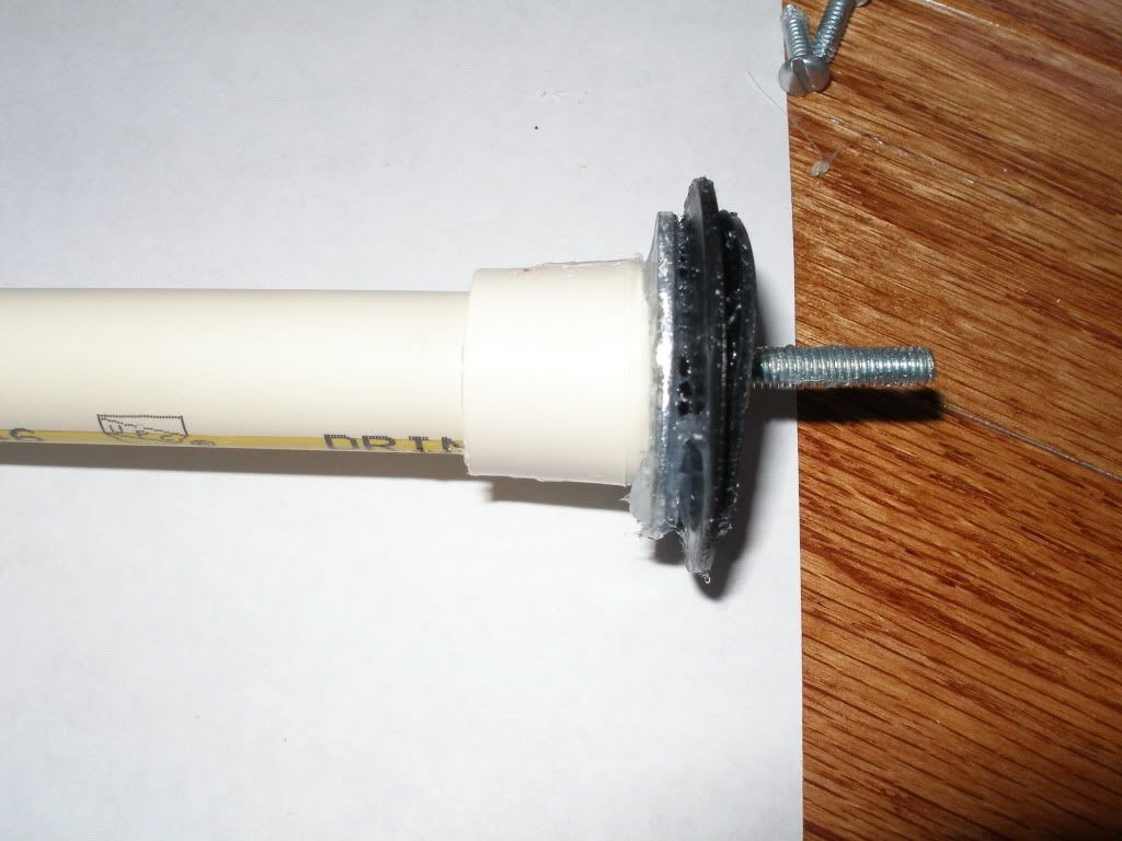
Components from left to right: 1/2" CPVC endcap, 1 1/4" steel fender washer, 1 1/2" neoprene washer, 1 1/4" neoprene washer.
Here is a view of the notch in the plunger rod, which the coupler fits into.
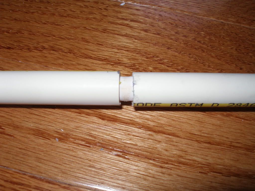
The notch is created by cutting the 1/2" CPVC plunger rod at the point where you want the notch, wrapping e-tape around a 7/16" wooden dowel rod, then super gluing the rod into either side of the plunger rod, but leaving ~1/2" exposed, to create a gap/divide.
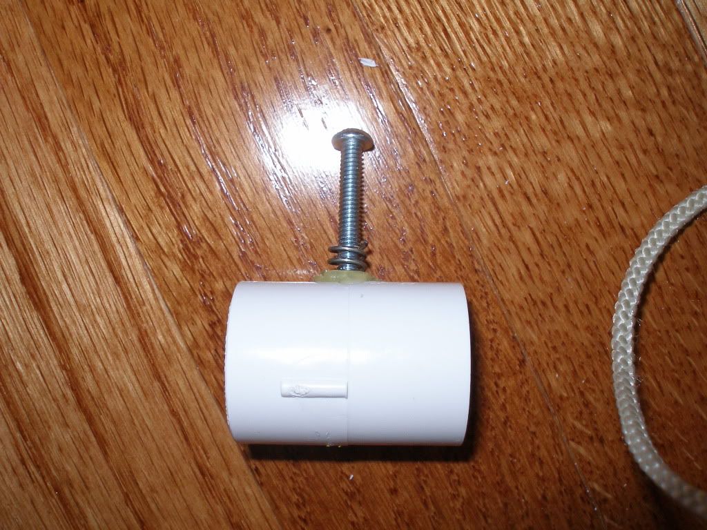
Here's a view of the catch piece and spring:
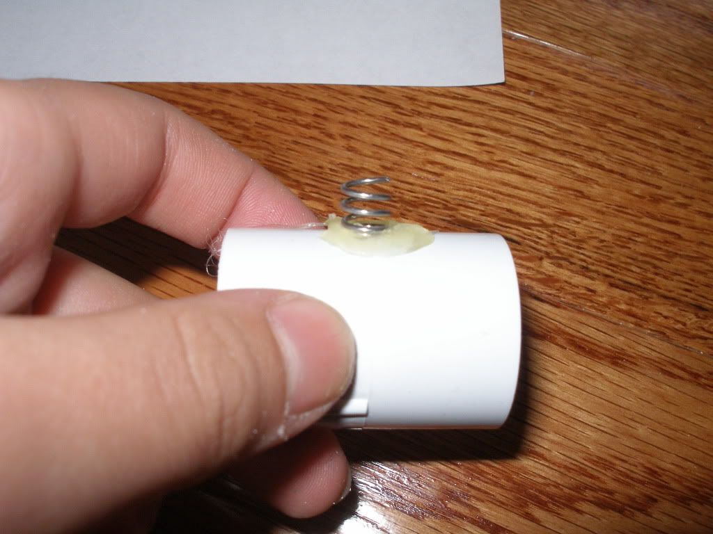
The spring is a strong industrial spring (that the catch screw can thread through), which is cut down to about 1/4", then hotglued to the top of the coupler, directly above the hole for the catch screw. The hole for the screw is drilled straight through the center of the coupler, and the screw is screwed into the coupler untill the bottom is flush with the groove.
Please note that the hole in the plunger tube for the screw to go through MUST be big enough to allow quite a bit of "wiggle room".
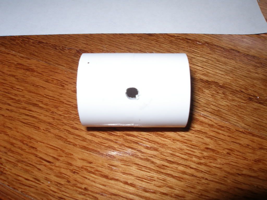
Here's a picture of the catch piece and hole:
If you use my current setup, with a 12" plunger tube (1 1/4" PVC) and a 12" 1/2" CPVC plunger rod, you only have enough room for about ~8 inches of spring area. You could, obviously, always make the PT larger, to house a longer spring like the [k26]. I used two Home Depot industrial springs, which were 4" each.
If you plan to use the same spring setup as me, you should make your notch about 3-4" away from the end of the endcap on the plunger rod.
I positioned my back endcap so that about 1/8" of it was sticking out of the back of the PT, for maximum possible draw. I positioned my coupler as tightly between the two endcaps as possible, so that I could, once again, have minumum space taken up by the assembly. I put the screws that secure the two endcaps in the MIDDLE of the endcap. The measurement from the middle of one endcap to the middle of the other ended up being 2 9/16" for me.
Conclusion
I feel that my goal was achieved. If you build this blaster, you will find that the catch movement is quite smooth. The one complaint I have is that the trigger assembly is not quite smooth/stable.
Features to fix in Rev. 2:
-Smoother trigger
-Smoother catch movement
-Less space taken up by the endcaps
-Maximum Draw length
-Shorter assembly time
The entire assembly of this blaster took me around 7 hours, but it should be easier for others, since I had to measure all the components out, and since I was the first to do this...
I will be posting a video of the function some time later this week. I cannot take ranges at the moment, due to the fact that the goop on the bushing is still drying
 , but the ranges should be similar, or a little less than SNAP ranges, since I have less draw. However ,the catching and trigger pull is MUCH smoother on this blaster than on my SNAP.
A writeup of how to make this will most likely be made, if requested.
Any questions/comments/suggestions may be posted here, or directed to me through PMs. I apologize if this overview was a bit unclear-it is my first overview/writeup post.
Please post any suggestions for the name of this design...they will be considered, since I can't think of any at the moment.
--Chaos
Edited by ChaosPropel, 05 December 2010 - 01:05 PM.


