Jump to content


Photo

Smdtg Trigger

Fully Illustrated

12 replies to this topic

#1 imaseoulman

imaseoulman

    Member

  • Members
  • 1,005 posts

Posted 11 September 2008 - 09:57 PM

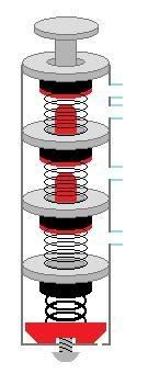
Alright, so I had a broken SMDTG trigger and I was curious how the check valves were set up, so as much as it pained me, I cut it apart piece by piece to see what tricks I could pick up from it. Being more familiar with the Big Salvo set up, I was a little surprised by the inline set up, but it is a good solid desing and I think a home-made would be farily feasible, especially if you can machine parts (cough, slug, cough). So, here's a diagram of the SMDTG trigger:

Posted Image

So, air enters the assembly from the top-most tube opening. The air builds up pressure and the spring that holds the seal in place is compressed, allowing the seal to open, and air builds up in the second chamber until the spring in the third chamber compresses, allows the seal to open, and then air builds up pressure in the third chamber.

If you continue to increase pressure (pumping more) then the Over-Pressure-Release-Valve will kick in. The spring that holds the bottom most seal in place is a bit beefier than the others. The screw acts as a sort of regulator on air pressure. The more you tighten it, the more pressure is required to compress the spring enough to open the valve (because the spring is being pressed more firmly against the seal; the screw pushes the red plastic cap which pushes the spring up against the seal).

After the assembly is pressurized, depressing the detonator slightly allows air to flow out the top of the assembly so there is back pressure in the two top-most tube openings, so the blast chambers attached to them will fire. This means that, theoretically, it wouldn't matter which tube opening air came in on; the first and the second would both work. I can't think of any reason why you would need to switch it, but maybe in a tight squeeze it could make a difference.

After air releases from the top chamber, the base of the detonator pushes against the red post of the next seal-post-piece. As you continue to depress the detonator, the base of the detonator presses hard enough against the post beneath it and causes the seal to open in the second chamber, creating back pressure and firing the next barrel. Continuing to depress the detonator will cause the second base piece to push against the bottom post and force open the last seal, allowing air to again rush out, creating back pressure, and firing the last barrel.

This is a simple and effective design that I really think could be easily replicated with the proper tools. My goal, however, is to make a homemade version out of very basic modding tools. The length of the detonator post only needs to be long as the combined distance between each base piece and the tip of the next post. This allows the trigger pull to be very short, especially when compared to the Big Salvo and other blasters that don't utilize this inline system.

I hope this explanation was understandable. If you have any questions, feel free to ask.

edit: I just realized this should probably be in General Nerf or something. I'm just not used to creating topics in those forums.

Edited by imaseoulman, 11 September 2008 - 10:22 PM.

  • 0

#2 Split

Split

    Member

  • Members
  • 1,771 posts

Posted 11 September 2008 - 10:37 PM

Wow. So much thanks for all of the work you put into this one. It's very well illustrated and explained. I understood all of it, and I only have 1 course of college physics under my belt. I do agree that this would not be overly difficult to reproduce as well. You could also do as many blast chambers as you wanted, correct? That leaves open a lot of possibilities.

Again, much props. :o
  • 0
Teehee.

#3 mintee

mintee

    Member

  • Members
  • 263 posts

Posted 11 September 2008 - 11:04 PM

I wonder if it is possible to chop off the bottom part and just seal it so that there are absolutely no pressure regulators. Props for the excellent diagram.
  • 0

#4 CaptainSlug

CaptainSlug

    Resident Mad Scientist

  • Administrators
  • 4,763 posts

Posted 12 September 2008 - 02:05 AM

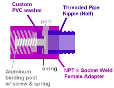
Might be possible to make these with binding posts, o-rings, and pipe parts.
Like so
Posted Image
You just make duplicates and screw them together then seal off the last one with a threaded pipe cap.
The trigger end of the unit could be made with a pipe cap rather than a female adapter.

You could also do as many blast chambers as you wanted, correct?

You're limited in total length since each successive valve requires more travel from all of the previous valves in order for it to be reached.

Edited by CaptainSlug, 12 September 2008 - 03:05 AM.

  • 0
The little critters of nature, they don't know that they're ugly. That's very funny, a fly marrying a bumble bee. I told you I'd shoot, but you didn't believe me. Why didn't you believe me?

#5 imaseoulman

imaseoulman

    Member

  • Members
  • 1,005 posts

Posted 12 September 2008 - 04:12 AM

You could also do as many blast chambers as you wanted, correct?

You're limited in total length since each successive valve requires more travel from all of the previous valves in order for it to be reached.

Yeah, with the dimensions used in the SMDTG, i think you might be able to squeeze out up to six shots, but that's pushing it. (Obviously not all dimensions would be the same, but the same basic size + added length)

Slug, are those parts all available on McMaster? I'm going to look into this. That design looks much cleaner than anything I've come up with in my head so far (but then again, so is pretty much everything you do). I don't have much experience working with homemade seals, so I'll probably get it wrong a few times before I get everything to mesh right. The idea is to keep cost down below the cost of buying an SMDTG.
  • 0

#6 CaptainSlug

CaptainSlug

    Resident Mad Scientist

  • Administrators
  • 4,763 posts

Posted 12 September 2008 - 05:32 AM

Slug, are those parts all available on McMaster?

Everything except the PVC washers. Which I could make on the lathe at work if you want them.
You'll need a pipe tap if you want to thread the ports for fittings.

Edited by CaptainSlug, 12 September 2008 - 05:42 AM.

  • 0
The little critters of nature, they don't know that they're ugly. That's very funny, a fly marrying a bumble bee. I told you I'd shoot, but you didn't believe me. Why didn't you believe me?

#7 Blue

Blue

    Member

  • Members
  • 2,222 posts

Posted 12 September 2008 - 01:21 PM

Thats cool. A triplestrike is like that only the trigger pushes a o-ring plunger thing down the shaft, there are no springs either.

Edited by Blue, 12 September 2008 - 01:21 PM.

  • 0

#8 Draconis

Draconis

    I am not Lord Draconical

  • Members
  • 2,712 posts

Posted 12 September 2008 - 01:30 PM

How strong are the stock springs? Weak enough that we could use something lightweight, like Mav/DTG/Firefly AR springs?
  • 0
[15:51] <+Noodle> titties
[15:51] <+Rhadamanthys> titties
[15:51] <+jakejagan> titties
[15:51] <+Lucian> boobs
[15:51] <+Gears> titties
[15:51] <@Draconis> Titties.
[15:52] <+Noodle> why is this so hard?

#9 imaseoulman

imaseoulman

    Member

  • Members
  • 1,005 posts

Posted 12 September 2008 - 08:51 PM

Thats cool. A triplestrike is like that only the trigger pushes a o-ring plunger thing down the shaft, there are no springs either.

They're almost entirely different. The only similarity in function is that it allows air to escape out of the assembly. The triplestrike trigger is not nearly as reliable as an SMDTG trigger.

How strong are the stock springs? Weak enough that we could use something lightweight, like Mav/DTG/Firefly AR springs?

I haven't looked at an AR spring for quite some time, but I think it would work. The springs in the SMDTG trigger assembly may be just a little bit stronger than an ar spring, but not much.

I'm kicking around a few ideas still on how to do this. I really like CS's design (seems very easy and sturdy) but I don't have access to the necessary tools. I'm hoping to make a crude version that still functions well...we'll see how it goes.
  • 0

#10 doubleshot

doubleshot

    Member

  • Members
  • 311 posts

Posted 12 September 2008 - 09:09 PM

Is there any name for this valve/trigger set up? This is about the most interesting thing I've seen on these forums.
  • 0
92% of people make up statistics. If you're one of the 8% who don't, put this in your signature

#11 imaseoulman

imaseoulman

    Member

  • Members
  • 1,005 posts

Posted 12 September 2008 - 09:36 PM

Is there any name for this valve/trigger set up? This is about the most interesting thing I've seen on these forums.

Other than SMDTG trigger assembly?
I think of it as an "Inline Check-Valve Series w/ Push-Button Override." But really, it is essentially three check valves in a series with the added option of manually overriding it with a push button. Another option is "Inline Pushbutton Back-Pressure Trigger."

Does anybody know of an actual valve that works like this? That already has a name? If not, your ideas on what to call it are just as good as mine, but in the mean time, I'm going to refer to is an SMDTG trigger assembly.

Oh, wait, I just thought of another, "Multi-Port Push-Button Trigger." Or MPPB trigger for short.
  • 0

#12 Galaxy613

Galaxy613

    Member

  • Members
  • 999 posts

Posted 12 September 2008 - 09:36 PM

Is there any name for this valve/trigger set up? This is about the most interesting thing I've seen on these forums.


We should probably call it the Inline Trigger System. *Edit* MPPB works too.

Very nice investigating imaseoulman, and damn CS, that is AWESOME and modular. How much would each section cost?

Edited by Galaxy613, 12 September 2008 - 09:38 PM.

  • 0
[Former Caretaker of the Guru Mk2]

#13 Draconis

Draconis

    I am not Lord Draconical

  • Members
  • 2,712 posts

Posted 12 September 2008 - 09:53 PM

We should probably call it the Inline Trigger System. *Edit* MPPB works too.

Very nice investigating imaseoulman, and damn CS, that is AWESOME and modular. How much would each section cost?


I agree guys... This is awesome, and the modular valve system is pure genius, CS.

I do see the solvent welding advantage of PVC washers, but couldn't one simply use nylon or metal washers that are readily available? And just use Goop or silicone?

1/2" female PVC adapters are $0.50 or so. The ones from electrical sections (conduit), are even cheaper, but aren't usually pressure rated. The short pipe nipples would also be less than $1 each, and could be cut in half, to be used in two sections. I'll have to look up the washers and binding posts.

Edited by Draconis, 12 September 2008 - 10:01 PM.

  • 0
[15:51] <+Noodle> titties
[15:51] <+Rhadamanthys> titties
[15:51] <+jakejagan> titties
[15:51] <+Lucian> boobs
[15:51] <+Gears> titties
[15:51] <@Draconis> Titties.
[15:52] <+Noodle> why is this so hard?


1 user(s) are reading this topic

0 members, 1 guests, 0 anonymous users