

Motors are the life of these things. Once you lighten and balance the flywheels (you won't need to worry too much about the flywheels slowing down if your motors wind it right back up before you can pull the trigger again), the only moving part left to work with is the motors
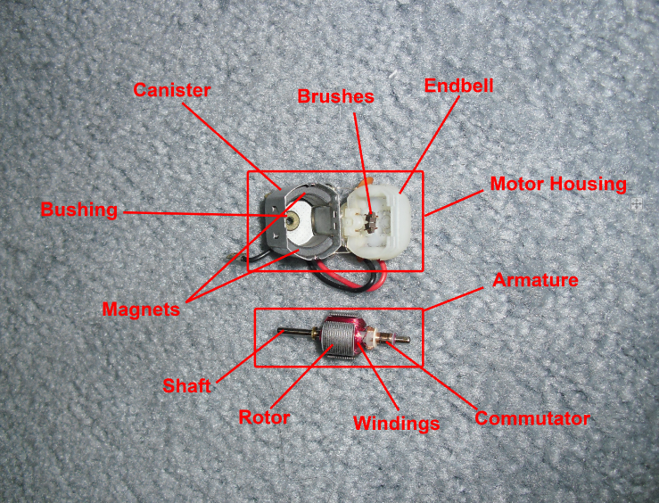
BASIC GUIDE TO MOTOR ANATOMY
First I will explain the parts of a motor:
-Commutator: This is the copper part that transmits the current running through the motor into your windings. It also rotates along with the core of the motor in order to regulate the polarity of your windings' magnetic field as it spins. Sometimes (on rare occasions) you will come across silver coated commutators, which are very power efficient.
-Armature: This thing is the heart of your motor. It spins along its 2 mm central shaft and contains the rotor, the windings, and the commutator.
-Brushes: These are part of the endbell and they contact the commutator in order to transfer current through it. They should be mounted to springy arms that hold the brush material, which varies from regular copper(lowest quality) to silver-doped carbon(highest quality).
-Bushings/Ball Bearings: These are what the armature shaft rides on. If you have bushings, it's a sliding interface with the shaft's surface. if you have bearings, you have a ball bearing to reduce kinetic friction into rolling friction (which is much much less).
-Magnets: These create the magnetic field necessary for the poles of the armature to magnetically push against. They come in a variety of strengths.
-Can: The metal part of the housing which contains the magnets, magnet retaining clips, and bushing or bearing.
-Endbell: The plastic part of the housing which holds the brushes and sometimes a bearing or bushing (depending on quality).
here is a diagram:
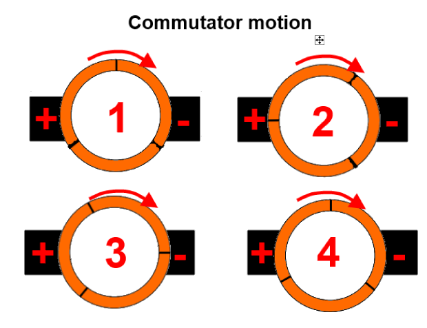
The motion of a commutator in our motors switches the pole polarities in our motors by using gaps in the copper outer coat of the cylinder. As it rotates, the commutator is contacted in different parts of its surface, transmitting the current through the armature's coils appropriately. Shown below is the motion of the commutator against the brushes (brushes are black, commutator copper is orange):
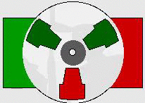
As a motor spins, the commutator polarizes each coil separately and causes the polarization of each pole, which rotates the rotor inside the magnetic field. In this gif, the green polarization is attracted to the red magnet, and repulsed by the green magnet; same with the red polarization.
 animation taken from online source
MODIFICATION:
Our nerf flywheel blasters run on two 130-sized DC machubi motors. There are limits to the motors used by nerf in that they use somewhat cheap brushes, small-diameter commutators, and high-wind count. This along with the wire resistances from all of the extra locks and electronics switches will reduce the performance of your motors (though it will be more safe for them).
The motors in the flywheel blasters aren't matched and balanced. You know how you get that oscillating tone as both motors wind up? (especially pronounced when you overvolt the blaster) That tone is caused by different power curves in both motors. Neither accelerates the same as the other, and neither tops out at the same RPM, producing what are called "beats". This phenomenon occurs when two sound frequencies are very close to each other but not quite the same; the difference in frequency is heard as a "beat".
Take for instance a motor rotating at some RPM that produces a sound at 300Hz. Then you have a second motor spinning slightly faster, producing a sound at 310Hz. when these two pitches travel towards you, they will periodically interfere with each other, creating constructive peaks and destructive cancellation in the sound. The result is a 10 Hz beat frequency, heard as an undulating intensity in noise. The slower the beats, the more in sync your motors are.
The solution is to ditch the armature winding that the manufacturer as opted for in favor of more balanced windings from a different section of the hobby world: rc race cars. There is a wide array of motors and parts in this hobby that can be brought into our own hobby. For starters, having in sync motors means needing to make the variables between your two motors as small as possible. For that purpose you will want to upgrade to motors that have ball bearings on both ends. The tight tolerances of steel ball bearings give consistent friction values for all applications. The wiring and the noice-cancelling will also need to be identical (so things like voltage spike smoothing done with capacitors). Lastly, your armature and brushes will need to be identical. This proccess entail 1 of 3 things: either you buy premade high performance motors, buy parts for high performance motors and put it together, or buy basic parts for motors and do the armature winding yourself (usually you will want to do what's called a pattern wind. I'll elaborate later.)
You can buy and use two of any brushed DC motor made for 1:28th to 1:24th scale rc racers as well as Tamiya 4wd racers except for the ones labelled 17mm (those are a bit specialized and don't fit the normal dimensions). Widely known platforms whose motors are compatible with our blasters are Kyosho mini-z, radioshack xmods, and Tamiya 4wd racers.
Companies that produce premade motors and parts: Auldey, Tamiya, RC Atomic, PN Racing
Places to find materials: Radioshack, or any other electronics parts store, Amazon, ebay.
Some blasters suffer from slow windup. This lag is often the main reason why people opt out of using flywheel blasters. It's debilitating in some situations not to have instant reaction-time firing.
The solution again comes from that world of oh-so-developed race motors. Torque is what you're looking for here. The main two things affecting the torque of your motor is the magnets and your windings.
Magnets come in 3 main strength classifications (from weakest to strongest):
-An-Isotropic: lowest quality, weakest field strength
-Isotropic: standard quality, decent field strength
-Neodymium: higher quality, highest field strength.
Racers use neodymium magnets to give a maximal bump to torque at the cost of a little max rpm. This is totally fine as a tradeoff for us as well. I currently am only aware of 2 to 3 different neodymium magnet kits for these little motors. Some motors are sold with neodymium magnets and ball bearings preinstalled as well. They aren't that expensive to get, and install pretty easily if you have ever successfully taken apart and reassembled a motor.
Windings affect torque by the basic principle of solenoids: B=uNI (Magnetic field equals the magnetic permeability times number of turns times current). The more turns(loops) around each arm of the armature, the stronger your magnetic field will be and the more torque you're going to get. The tradeoff here is that if you have more loops, the inductance also creates a stronger back-emf, lowering your max RPM. This is because when energized, a motor will accelerate until the total friction and back emf are equivalent to the emf applied to the motor to motivate it.
So the idea is that the best nerf motor for close quarters would be one with a very fast windup with a decent max RPM, and the best nerf motor for a longer ranged flywheel blaster would be one with a decent windup and a very high max RPM.
Modifying motors is not really difficult at all, except for when it comes to the windings (if you're aiming to do the windings on your own).
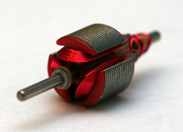
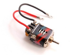
A common machubi motor will spin around 25000 rpm at 6 volts. This isn't too bad, considering that it will have anywhere from 65 to 55 turns around each arm of the armature. However, they are not suited for high performance work. The commutator is small diameter, which, if given high voltages will risk glazing and burning. This is why our typical motors don't withstand more than 11.1v in most cases. What you want in a higher voltage high performance motor are large diameter commutators such as this one where the copper cylinder is much thicker and beefier:
 (taken from pn racing stock photos)
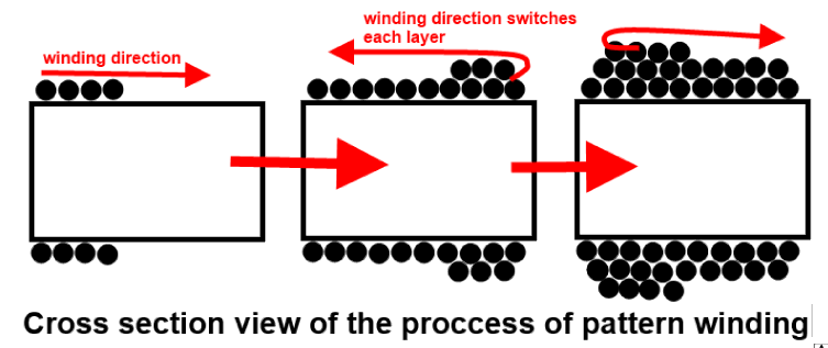
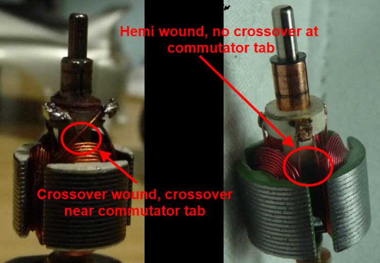
Windings: the point of winding patterns is to create a consistently generated field by minimizing winding randomness. Machine manufactured motors will generally have pretty consistent, but still have a bit of inconsistency. The main fix to this is pattern winding. This means following a pyramidal stacking pattern of each loop of wire. You'll want tight winds to minimize variation in winding lengths. You will also want to count carefully the number of turns on each loop and VERY carefully wind 1 arm of the armature at a time, and always in the same direction. As you finish a single arm you'll want to strip some enamel coating off of the wire to expose the copper for soldering to the tabs of the commutator. A good solder joint will not heat up and melt under stress. Below is a diagram of how pattern windings work and a picture of the results of pattern winding. This particular example of pattern winding uses crossover ends (I'll include a picture showing the differences to that as well)
Crossover winding vs Hemi winding: crossover crosses the wires when ending each pole, hemi does not.
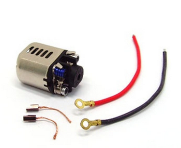
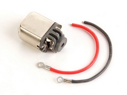
For lower and more consistent friction, use ball bearing motor casings. Most ball bearing motor casings won't look too different from a standard motor casing though some will have interesting cooling features or endbell designs to increase efficiency and reduce heat:
(stock photos of products)

Last is the batteries:
Trustfires suck. Don't get me wrong, they work. The only thing Trustfires have that polymer won't do is instant install where some Trustfires will install without modification whatsoever. It's not enough of a justification in my own opinion, when all I need to do is install a plug and snip off the battery dividers to make the blaster accept my 7.2v packs, which despite not being very high voltage, have high current and can spool the motors much faster than the Trustfires I tried. The problem with these drop-in batteries is that they don't have the current capabilities to really push the performance of our blasters. This is why I use lithium polymer for all my overvolt mods. Lithium polymer battery setups at cheapest will run about 10-20 USD to purchase and install (including the charger if you know where to buy these things from! hobbyking woot!) with tools I assume most modders already have: soldering iron, screwdrivers, cutting implements. Trustfires are not much safer since BOTH are lithium based rechargeable batteries. Lithium ion (Trustfire's battery chemistry) fires are just as bad as lithium polymer fires. One of these can power your blaster very effectively at a high amp draw, and will not bog down under high demand.
.jpg) (stock photo from hobbyking)
(stock photo from hobbyking)FOR THE TECHNICALLY MINDED: I've created an additional guide on controlling motors with what's called an H-bridge, and transistors rather than physical switches that sometimes cannot take the current draw.
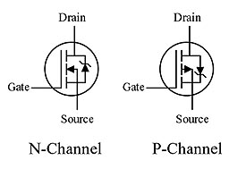
A MOSFET is a Metal Oxide Semiconducting Field Effect Transistor.
Generally they come in 2 types. n-channel and p-channel. These essentially are high speed switches that can be turned on and off at speeds that are impercievable by humans. Let's go through them.
N-Channel FET:
3 leads coming from the transistor:
-source lead connected to ground, or negative,
-drain lead is connected to the load's negative tab. (or whatever is upstream)
-gate lead's signal controls the on/off state of the transistor, a low signal meaning off, and a high signal meaning on.
P-Channel FET:
Like the N-channel, 3 leads coming from the transistor, however different connections and behavior:
-source lead connected to positive
-drain lead is connected to the load's positive tab (or whatever is downstream)
-gate lead's signal controls the on/off state of the transistor, a low signal meaning on, and a high signal meaning off.
In this manner, these gates can be used on their own without making an H-bridge if you do not desire the polarity on the motors to be reversed for braking. Continuing though, reversible motor control runs on what's called an H-bridge. This is a combination of 2 N-channel mosfets and 2 P-channel mosfets to make an H-shaped formation. Here is a circuit diagram:

How this works is that when both the left pair of transistors (the n and P channel fets) and the right pair of transistors are given a low signal, the circuit is off with both n-channel transistors off, and p channel transistors on (does nothing since there is no voltage potential difference).
When the left side's gate signal goes to high, it turns off the left side p-channel and connects the n-channel on the left. since the right side's unchanged, the current passes through the conencted p-channel on the right side, through the load in the middle, and then down through the n-channel to ground.
When the left and right side signals are reversed, the current travels through the load in the opposite direction. this means it runs in reverse, if it's a brushed dc motor.
Conveniently enough, if you don't want to build it super beefy, you can use IC's that are generally intended to be used for H-bridges. I've provided the datasheet here for one that has both an n-channel and p-channel integrated and diode-protected: http://www.vishay.co...70717/70717.pdf
Duty cycle:
this is where variable speed control comes from. when duty cycle = 100%, there's no oscillating between high and low signals for either the left or right side of the h-bridge. this means that maximum current passes through.
at 50% duty cycle, half of the time, the signal is high, and the other half of the time, it's low (cycling between high and low evenly)
at 0% duty cycle, the circuit is completely turned off.
This is a fairly easy to grasp concept. It literally is how much percentage of the signal's time is spent on a high signal. How does this vary speed? it switches so quickly on and off, that the motor sees an analog-like varied current input. It then acts like it runs at whatever percent of max voltage that the duty cycle is at.
There you have it: MOSFETs. You can use them as just solid state switches since they don't undergo electric arc wear, and are more durable under higher voltages and amperage, or you can use both that quality and the variable duty cycle to make your motors variable speed without losing as much energy to heat. You generally will need to step down the battery voltage if running above 6V so you don't overload the gate pins.
Cheers and happy new years!
Edited by RedFear, 16 January 2015 - 12:26 PM.


