
Hello everybody!
My friends have been pestering me to share my latest project with you all, as they believe it is so cool that just can’t keep it to myself. I will leave it to you to decide.
HISTORY
Before we go into the details of how this mod, let me give you a smidgen of history. A close friend of mine recently started hosting Nerf games on the weekends and once our group started growing, he decided to invest in a Rapidstrike CS-18 Nerf Blaster. He had seen Coop772’s youtube video, showing how he modifying his Rapidstrike, and was interested in doing something similar.
Knowing that I was into electronics, he asked if I would be willing to look it over with him, and see what we could do to boost the rate and speed of fire. (Only without burning out the motors) We started with a simple voltage boost to run the motors faster. But after looking at how this blaster was made, and seeing all of the components, I started to realize just how much potential this blaster really has.
So, I purchased my own, and the project began.
About Me
I am new to this sport, but it I find it is very similar to paintball. And although it has been quite a while since I’ve played, I find that many of the tactics apply. Just like many of you, I think Nerf and I will have a very bright and fun future together.
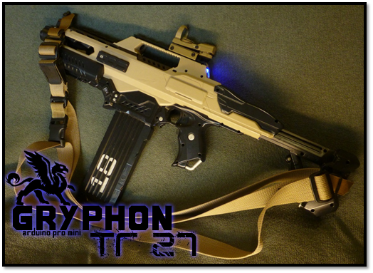
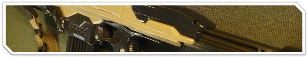
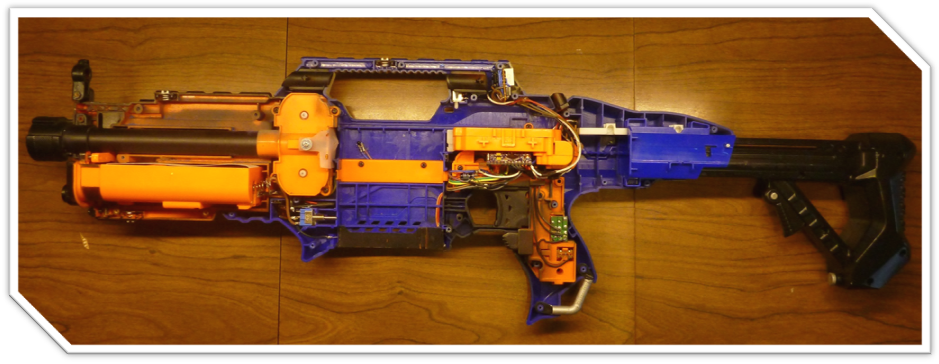
This is the TR-27 Gryphon. It is a fully modified Rapidstrike CS-18, featuring a microprocessor controlled double digit ammo counter that can automatically recognize and display the capacities of multiple types of magazines.
It has 3 unique modes; 3-burst, fully automatic, and "Precision Shooting" I have designed it specifically for functionality and game play, not necessarily aesthetics. Although I think the paint job was a pretty cool touch **grin**
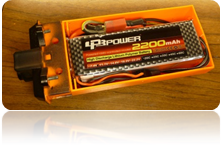
This blaster is powered by a Lithium-Polymer battery that is capable of boosting the flywheels up to full speed in 3/10th of a second, as well as achieve firing rates of nearly 7 darts per second.
This means you won’t have to wait for those flywheels to spin up before you can return fire, or spring from your ambush hiding spot. Unlike the original Rapidstrike, you won’t have to walk around with the flywheels running; giving away your position and wasting your battery life.
3-Burst Mode
3 DART BURST AT 7DPS
http://youtu.be/n2xjWE69xpA
Aside from just being cool, this mode was designed for attacking.
Snippet about 3-Burst: The 3-burst concept was made popular with the M16 assault rifle widely used in Vietnam. A fully automatic rifle typically has so much recoil, that after firing much more than 3 rounds, a soldier needs to stop, and re-aim. Failing to do this results in very poor accuracy, and is also a massive waste of ammunition. 3-Burst was designed to allow the soldier to re-aim between bursts, and to conserve ammunition.
Unlike the M16, the goal of the TR-27’s 3-burst mode is to push the blaster to its max, while still allowing enough time for the motors to cool down. Tactically, this is an excellent point and click style tool, almost eliminating the issue of dart inaccuracy. This is without a doubt my favorite in-game mode.
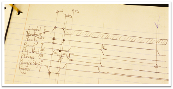
From standby, the first trigger pull will bring the flywheels up to full speed in 300ms (milliseconds) if the trigger is still held in at the end of the 300ms, it begins to burst fire. If not, the blaster watches for a trigger pull and keeps the flywheels up to speed for 2.5 seconds before going back to standby. The burst shot will immediately fire 3 darts at a rate of almost 7dps (darts per second), followed by a 300ms delay before you may repeat the process, and fire again.
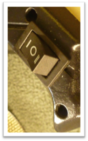
Mode selector switch set to burst mode
Automatic Mode
SINGLE OR CONTINUOUS STREAM OF DARTS AT A RATE OF 4 DPS
You can find the rest of my videos for this blaster on youtube
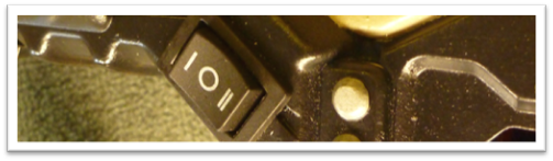
Mode selector switch set to auto mode
This mode is designed specifically for defense and allows you to conserve your ammunition while still keeping your foes hiding behind their cover.
Again, from standby, the first trigger pull will bring the flywheels up to full speed in 300ms. If the trigger is still held in at the end of the 300ms, it begins firing. After the dart has been fired, the gun has a 100ms delay before you may repeat the process.
Thanks to my friend’s input on the matter though, you have 2 options for continued fire after the flywheel is up to speed. It’s sort of a mix between automatic and single fire. If you hold the trigger down, the gun will begin another shot at the end of the delay from the previous shot.
Alternatively, you may pull the trigger repeatedly, and the blaster will count how many times you have pulled the trigger, and add to the firing cue. This means, starting from standby, you could pull the trigger 19 times, as fast as you can, and the blaster will spin up and fire all 18 darts.
Note about delays: Both 3-burst and auto have delays at the end of either a 3-burts shot, or a single fire/full auto shot. This is done on purpose for two reasons. First is so they both take roughly 4.5 seconds to empty an 18 round mag. Second, and more importantly, the delays are to keep the motors from overheating and either shortening the motor’s life, or even burning them out. Even though the two modes empty the mag in the same amount of time, they both have their strengths and weaknesses.
"Precision Shooting Mode"
2 DART BURST WITH THE FLYWHEELS RUNNING AT ABSOLUTE MAXIMUM SPEED
You can find the rest of my videos for this blaster on youtube
Yes, we added "precision shooting" mode! This was born from my fond memories of playing Team Fortress Classic with my brothers. I was (you guessed it) the Precision Shooter, and I simply loved having showdowns with my brother (who was also a Precision Shooter), holding down the mouse button as the gun charges, waiting to see his head, and BANG! I like to think I beat him more often than he beat me, but I might just be trying to fooling myself.
Anyways, people often develop a false sense of security at a distance as so many darts fall short, or are just slow. This mode is designed to take advantage of that mindset. The higher speed that the dart travels through the air, combined with the fact that it bursts 2 darts, makes this mode much harder to dodge. A dart at this speed can really pack a punch, and the closer to the gun you are, the more punch you get, so I gave this mode a long spin up time to deter people from using it in confined/up close spaces.
Like TFC, this mode operates in the same way you would hold the mouse button down to charge the gun. From standby, you hold the trigger down, and the blaster begins to spin up the flywheels. In 3 seconds, the blaster will reach its full speed, running the motors at the full 12 volts, and will continue to run at that speed for 2 seconds longer. At any time during the spin up process, you may release the trigger, and the blaster will fire the 2 darts, and then delay 2.5 seconds before you may repeat the process or switch modes. Again, this delay is to prevent the motors from overheating. To prevent jams, the blaster will not fire on trigger release until it reaches its minimum speed, to ensure the dart won’t get stuck in the barrel or flywheels.
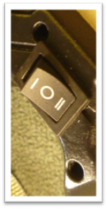
Mode selector switch set to "precision shooting" mode
Empty the Gun Mode
FIRES EVERYTHING AS FAST AS IT POSSIBLY CAN
You can find the rest of my videos for this blaster on youtube
Naturally, when something as cool as the Rapidstrike is controlled by a computer, the thing to do is push it to its limits, and see just how fast one can empty the gun. And in that vein of thought, I made “Empty the Gun” mode. With the throttles opened all the way, this TR-27 can empty an 18 round mag in as little as 2.7 seconds. Later in the project we achieved 2.2 seconds (little over 8 shots per second) However the smell of ozone made me think that this was putting the motors at risk of burning out.
This mode is limited in the following way. First, once you pull the trigger, it runs until it is empty. Second, it will only work with marked mags. So at most, you can only do a 35 round mag in one go. Third, you have to enter a code (sequence of trigger and warmup trigger pulls) in order to activate this mode. And it takes so long to enter the code that the motors have plenty of time to cool down.
Like I said, I designed the TR-27 for functionality and game play, and this mode is no exception. It serves little to no purpose in-game because it drains all of your ammo, and requires a lot of down time to protect the motors from burning up. However, the pure intimidation factor gives you quite the tactical advantage. Simply fire off a mag in this mode before game play starts, and everyone will have that image in their minds for the rest of the day; especially if they are on the opposing team. (Am I sneaky or what? **Evil Laugh**)
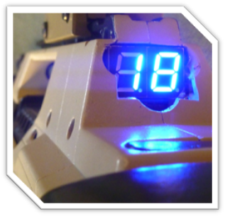
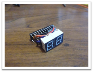
AMMO COUNTER DISPLAY
The TR-27 is fitted with two common cathode 7-segment displays in beautiful blue. You may turn off, or set the display by simply sliding back the access cover, and pulling the trigger. It has been programed so the first trigger pull will turn off the display, and every subsequent pull will increment the screen’s brightness up through the 15 levels of brightness. This way, you can quickly turn off your display if you find yourself trying to hide in a dark place.
Level 5 is pretty nice indoors; however I find that the light can be distracting if you are sighting down the top rail or through the red dot sight. Indoors, I typically play at brightness level 2. Level 15 is super bright, and great for outdoor game play when you are out in the sun.
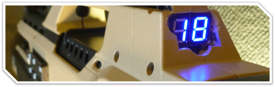
Ammo Counter after inserting an 18 round magazine
MAGAZINE DETECTION
Upon insertion of a marked magazine, the blaster will detect that ammunition is available, and depending upon the type of mag, will automatically set the ammo counter to the capacity of the mag. If an un-marked mag is inserted, the blaster will still detect that ammunition is available. However not knowing what capacity it holds, it starts the ammo counter in count up mode. This way when you play with your friends and use their mags, you can at least know how much ammo you have fired out of unmarked mag.
To date, the blaster is capable of recognizing 6, 10, 12, 18, 25, and 35 round mags after they have been “marked”. Marking a mag is very simple. There are 3 magnetic sensors inside the blaster that read the presents or absence of the magnets, and can then determine what capacity it is. (I am considering adding a 5 round clip for those of you who have done the “mini-clip” mod on your 6 round mags.)
From here on in, this stuff gets a little dry for most people. However if you are technically minded, want to learn something new, or just really excited about this blaster, read on!
SAFETY, MALFUNCTIONS, & ERROR CORRECTION
Slow Ammo Feed: The blaster uses infrared to watch the ammo at the top of the magazine, and will halt firing if no ammunition is available. Slow feeding occurs if your darts are either falling apart, or have been loaded in the mag in such a way as the tips rub up against the front edge of the mag. Consequentially, they do not feed as fast as the blaster is able to fire.
Piston Fails to Stop Soon Enough: There are times when the piston will fail to stop on time, and will coast back into the firing chamber. If the ammo has expired, then the blaster will auto correct by running the plunger at low speed until it has seated back in the ready position.
In the cases where there are still darts available to fire, the blaster ceases to fire, and indicates the malfunction to the user by blinking the ammo counter on and off. This malfunction may be cleared by removing the mag, thus expiring the ammo and allowing the blaster to auto correct. However, there are times when the jammed dart stays in the chamber, preventing the plunger from resetting itself. If this happens, you only need to open the access cover, and remove the dart by hand.
Bent Dart Jams: A jam common to darts that are flattened/squished/or have limp necks is when the tip gets folded over just before entering the flywheels. I have not yet determined if this is due to the piston pushing the dart forward before it is all the way out of the mag, or if it is something else. I have however recently programmed the blaster to delay 30ms if it senses that no darts are available to fire. This should allow just enough time for the slow feeding dart to make it to the top of the mag, before the piston begins to fire again. I’ll try to let you know if I notice any improvement on the matter.
Slowing Speeds Due to High Shooting Volumes: This issue really isn’t an issue. But I thought you’d like to know that it has been taken care of. Each time the piston pushes another dart into the flywheels, the flywheel motors are supplied with a 50ms burst of high voltage in order to maintain a regular dart speed. As I will explain a little further on, Nerf solved this problem by supplying the flywheels with roughly 4.5volts for warm up and standby of the flywheels, and the full 6volts only when the trigger is being pulled.
Display Shows Gibberish: This has happened from time to time, and is relatively easy to correct. Simply reset the blaster by removing the mag, and flipping the on/off switch located inside the mag slot. The cause of this is electrical. I have been working for some time to eliminate this entirely, but for now it remains an occasional annoyance.
INTERNAL COUNTERS
The blaster has internal counters that record how many shots have been fired, and how many reloads have occurred. In further revisions, I will probably add more counters to record things such as jams, lid opens, time spent in each mode, etc… But please keep in mind, I already have over 300 hours invested in the 800 lines of code for this blaster. I’m embarrassed to say that I’ve worked on it so much that my wife has nicknamed it “the other woman”.
ELECTRICAL DIAGRAM
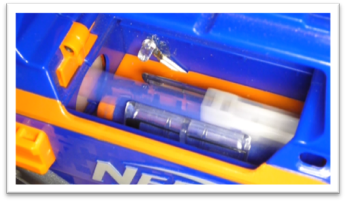
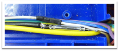
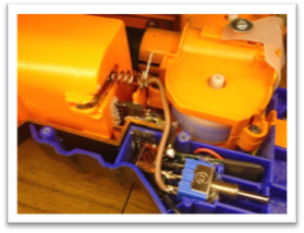
I started by diagramming the entire electrical system of the original CS-18 to see if I could incorporate any of the original wiring.
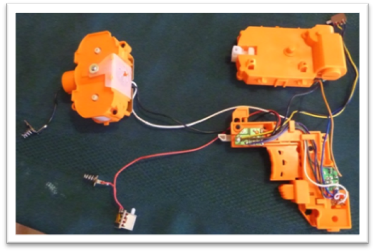
With a little fuse, all of the electrical components may be removed without unsoldering, or cutting any wires. It took time, but I eventually traced every wire, and made my diagram.
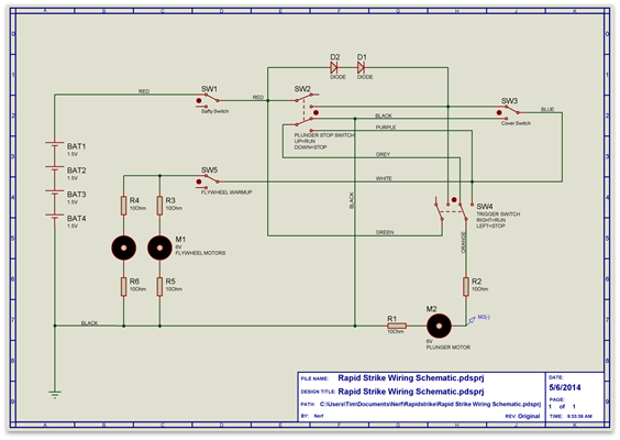
The diagram isn’t 100% complete, however it can give you a good understanding of how the blaster functions
The original Rapidstrike is designed so when the flywheel trigger is pulled, the flywheel motors are powered through the two diodes (D1 & D2) and the flywheels come up to speed. The diodes serve to lower the voltage a few volts so the flywheels don’t spin at full speed.
I’m sure the reason that Nerf has the diodes, is to prevent the flywheels from reaching a speed, under no-load, that would make lawyers uncomfortable. The full 6 volts are only applied when the trigger is pulled and the piston is running. It is the load of the darts that keep the flywheels from reaching that “uncomfortable” speed.
Besides, if they had run the flywheels at full, and then started feeding darts through it, the first 3 darts would be really fast, but then the continued load would slow down to what the blaster fires normally. This perceived slowing of the darts would ultimately lead to the user feeling cheated.
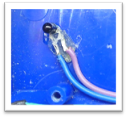
SIMPLE MODIFICATION
However, if you view it as getting 3 fast darts and 15 regular darts, instead of 3 normal darts, and 15 slow darts, then a very simple modification would be to bypass the diodes and prevent the voltage drop.
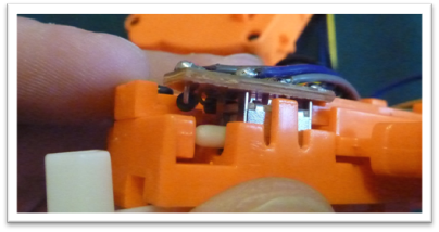
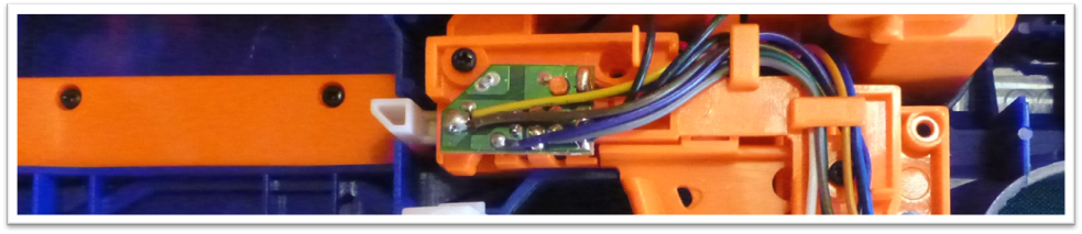
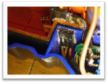
The simple mod would be to solder a wire running from where the yellow and brown wires connect, to the solder connection in the upper right corner of the PCB, where the red wire connects.
Bypassing the diodes should allow the blaster to spin up in far less time than previously. (But still not as fast as the TR-27 does)
Back to their design, it is interesting to note what they did for the piston motor. They are using a motor braking system to prevent the motor from drifting past the stopping point and entering the firing chamber after firing has finished.
Quick Snippet about motor brake: A motor brake is a method for quickly slowing down an electric motor. Motors are almost the same as generators. If you hand crank a motor, it will generate a current on its leads. And just like a generator, the greater the load, the more resistance you will have on the shaft. So, in order the get that motor to stop coasting as quick as possible, you need to put the maximum load possible on the leads. Which would be a direct short across the leads.
As it turned out, I didn’t end up using any of the original wiring; however the motor brake was a definite must in the TR-27.
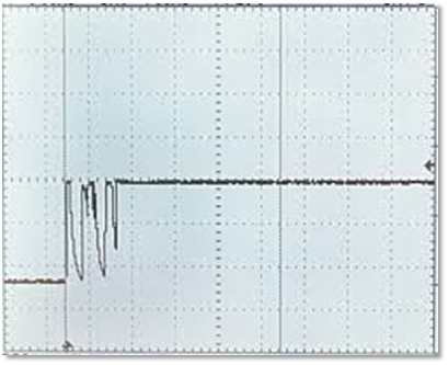
TR-27 MOTOR BRAKE
The piston in this system has been the most troublesome part in it. Yes, you can send some pretty high voltage to the motors to get them to go faster, but that doesn’t make them stop any faster. The TR-27 sends an 80ms burst of 12 Volts to the piston motor, immediately followed by 20ms of braking.
I have considered putting in a faster motor to run the piston, however it would still have the problem of not stopping soon enough.
Even with the pre-brake I’ve programmed in, my normal motor is coasting past its stopping point from time to time. My hopes are that I can either read more precisely where the piston head is located based on more than just the stop switch, or that I can burst the motor in reverse for a couple milliseconds, instead of using the brake. This is pending the installation of a full H-Bridge controller.
HARDWARE
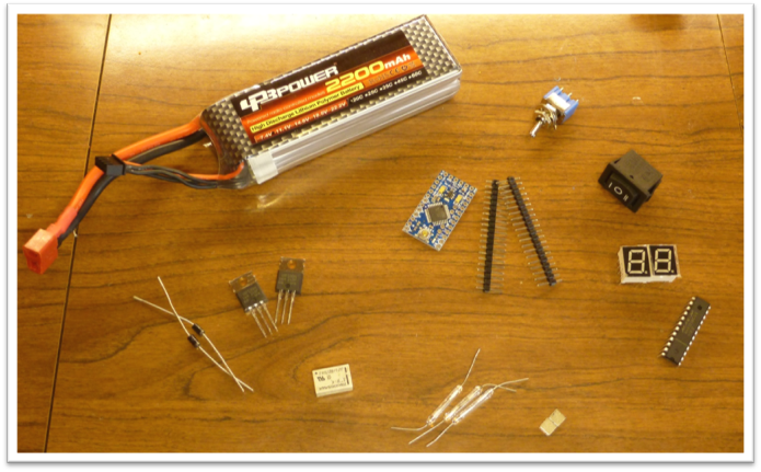
11.1 volt Lithium-Polymer Batter, Arduino Pro Mini, Power Switch, Mode Switch, 7-Segment Displays, MAX7219 Segment Driver, Diodes, MOSFETTs (to run the motors), Micro Relay (for motor brake), Magnetic Reed Switches (for detecting mag capacity), Neodymium Magnets (for marking the mags)
This list was missing the infrared sensor that is used to detect ammo, as well as a 5 volt regulator I have added in an attempt to solve the display gibberish problem.
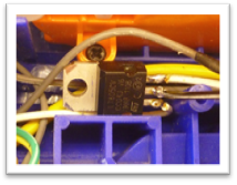
Infrared Sensor 5 Volt Regulator
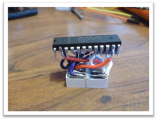
TR-27 MICROCONTROLLER & DIAGRAM
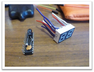
Like you read earlier, this blaster fitted with a microcontroller. It is an Atmega328P mounted on the Arduino Pro Mini.
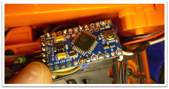
Microcontroller ATmega328P
This Arduino has no USB, and must be programmed with an external TTL device.
While this is a little more inconvenient, it does lower the cost of the board, and seeing as I ended up killing 2 of these boards in the making, I don’t mind so much. These may be purchased from the world wide garage sale, (eBay) as can almost every component that I have used in this blaster.
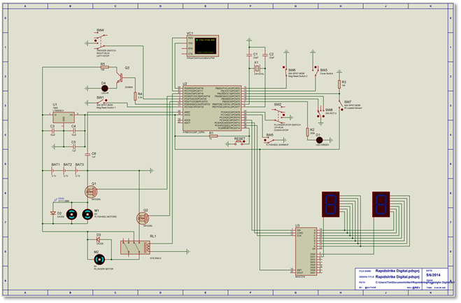
TR-27 GRYPHON electrical schematic
This diagram is very close to what I actually have in the blaster. There are a few minor differences because the program I used to diagram this doesn’t have all of the components I used in the blaster. So in this they are replaced with simple switches or something similar. The function remains almost the same.
Known Differences:
-There are now 3 reed switches detecting the capacity of the ammo.
-There is another board installed on the blaster that monitors the LiPo battery and discontinues use when the battery level is too low. This is to prevent the battery from being destroyed.
-Both of my flywheel motors are still powered through the built in resistors and the current limiter.
-There are capacitors installed on the 5 volt line to help prevent spikes that interfere with communication between the Atmega328 and the MAX7219 led segment controller.
-The IR LED no longer has a transistor, or is powered from the 12 volt rail.
SWITCHES
All of the original switches have been wired to the pins on the Arduino, and when pressed they pull the pins LOW (0 volts). In the programming, they are initiated as “INPUT_PULLUP”. This means the Arduino internally pulls the pin HIGH (5 volts), and watches to see if the pin is pulled LOW through external means.
Snippet about Microprocessors and switches: It is common practice in electrical design to use a pull down resistor to pull the pin LOW, and then have a button/switch that will supply 5 volts that will pull the pin HIGH when pressed. While the external pull down resistor method is probably a safer way to go; in that it will be less likely to be damaged by electrical shock. But my limited space makes the internal pull up resistor much more convenient. And because of the way Nerf built the switches, I feel pretty safe when it comes to electrical shock (Static electricity).
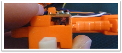
I had to remove all of the mechanical locks inside the trigger assembly in order to allow all of the switches to be used independent of each other.
There is one that prevents the trigger from being pulled unless there is a mag inserted. And there is another that prevents the trigger from being pulled unless the warm up trigger is held in.
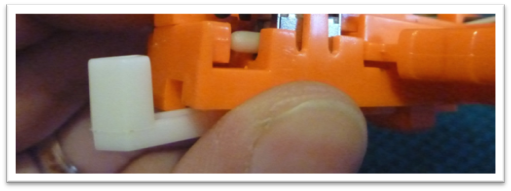
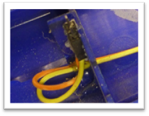
Trigger lock to prevent trigger from being pulled unless a magazine is inserted.
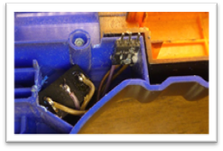
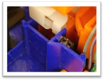
The main safety switch (SW1 in the original’s diagram) has also been removed, and that location is now used as the primary on/off switch for the blaster.
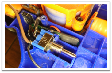
Rapidstrike’s Main Safety Switch TR-27’s Primary On/Off Switch
SWITCH PROGRAMMING
Okay, something you need to know about buttons/switches connected to microcontrollers. Microcontrollers are fast. Really fast. One of the problems that programmers must overcome is called debounce.
When a button is pressed, the voltage on the digital pin doesn’t just change from 0 volts to 5 volts. The button actually bounces, letting a fluctuation of voltage go to the pin. And since the microcontroller is so fast, it would see a single button press as 3 or 4 button presses.
Naturally there is a way to overcome this. Typically programmers have their code look at the pin, and when it sees a change, check back with it in a couple milliseconds. And if it is still the same, it assumes a button has been pressed, or released.
For the TR-27, it checks the buttons every 5 milliseconds, and it stores a running average of the last 10 readings. When the average of a button is higher than 5 it then considers the button to be pressed.
Not only does this take care of the debounce issue that happens when a button is pressed or released, but it also takes care of any mini spikes/dropouts that might happen while a button is being pressed.
In addition, not all switches/buttons are check all the time. For instance, the blaster doesn’t pay attention to the reed switches unless it detects that ammo is available or has been removed.
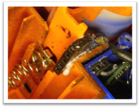
REED SWITCHES (MAGNETIC SENSORS)
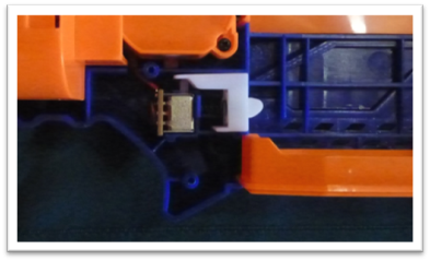
Two of the reed switches are mounted behind the mag guide, and third is mounted behind the wire cover. They interface with the Arduino the same as the others do, by pulling the pin LOW (0 volts), when a magnetic field is sensed.
With 3 read switches, the blaster may recognize as many as 7 different magazine capacities, depending on where and how many magnets are glued to the magazine. We have really put a lot of thought into every aspect of this blaster. To save on the cost of magnets, both the 6, 18, and 35 round magazines only require 1 magnet to be recognized. While the 12 and 25, being less common, need 2 magnets to be identified.
MULTI-INPUTS ON A SINGLE PIN
Funds and time allowing, future TR-27s will have all 3 reed switches connected to a single pin. This will allow me to pack even MORE stuff inside this blaster, as I am rapidly running out of available pins.
I have already made a working prototype for testing this new method.
The concept is basic. You have button that when pressed add a preset amount to a measurable total.
Button A = 1
Button B = 2
Button C = 3
And your total is 1, then naturally, button A is being pressed.
2 = B
3 = C
5 = B + C
6 = A + B + C
Simple, right? Well, not quite. If the total was 3, you wouldn’t be able to tell if buttons A and B are being pressed, or if button C is being pressed. The solution to this is to use multiples as your values. So A = 1, B = 2, C = 4. Now you can take the total, and figure out exactly what buttons are being pressed.
In electricity though, it gets a little more complicated, and the math becomes difficult to be exact. A standard “gold” resistor is accurate within 5% of its rated value. And you must have a common resister used as a pull-down resistor in the circuit as well. And to complicate things further, you can’t get resisters of exact multiples in rated value; at least not easily.
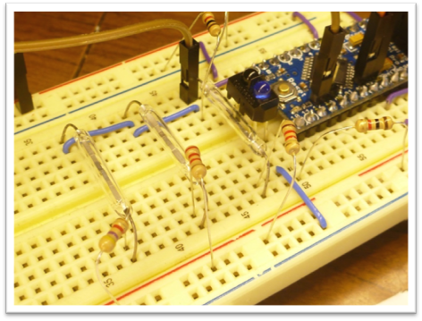
So, instead of trying to do the math, I made a funnel kind of measuring system instead. My reed switches are hooked to; 1.1k, 2.2k, and 4.7k resistors with a common 1k pull-down resistor. These are close to multiples, so I can still distinguish between buttons A+B and button C. The voltage is fed into the Arduino on an analog pin.
Note about analog reading on the Arduino: The Arduino board contains an 8 channel, 10-bit analog to digital converter. This means that it will map input voltages between 0 and 5 volts into integer values between 0 and 1023. This yields a resolution between readings of: 5 volts / 1024 units or, .0049 volts (4.9 mV) per unit.
After I made the prototype circuit, I pressed the buttons one by one in every possible combination, and recorded their values. Then I did the math to find the middle point between each reading, and then I arranged a large “if, else if”, block of code that “funnels” the reading into understandable information.
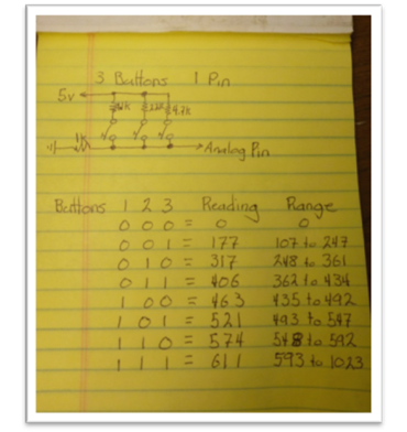
Not too bad for 3 switches, but the more you add to the system, the tighter your tolerances become, and the more possible combinations there will be to take readings on, and find the corresponding range.
INFRARED SENSOR
Originally I had used an IR sensor taken from the scroll wheel of a mouse, however now I have a smaller one that I bought in bulk from our favorite worldwide garage sale. Electrically it’s a rather simple sensor. It works exactly like a transistor (probably why they are known as photo transistors…), but instead of having signal lead, it uses infrared light to activate the gate.
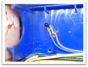
Meaning you hook one side to 5 volts, and the other to a digital pin on the Arduino that is being pulled LOW with a 10k resistor. When Infrared light enters the sensor, it sends a very small current into the gate, allowing the larger 5 volts to flow through the sensor, and into the pin on the Arduino.
Back when I was using the mouse sensor, I had a much larger Infrared LED, for sending the IR light to the sensor. In fact it drew so much more current that I had to power it from the 12 Volt line, because the onboard regulator on the Arduino wasn’t able to handle it. Later I realized I was burning up a lot of energy in the resistors I used to step the 12 Volts down to run the LED. So, in order to solve that, I added a transistor that would control the LED, so I could turn it on and off only when taking a reading.
It was a nice improvement, but the smaller ones are still better.
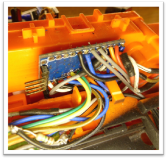
WIRING
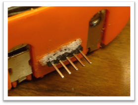
Nearly all of my wiring is on the right half of the blaster, just like Nerf did theirs. However I have 2 items located on the left side of the blaster that I have run wires to. The Infrared LED, and the mode switch; wiring for those run through pins that I have glued on either side. And when the blaster is assembled, they plug into each other very well.
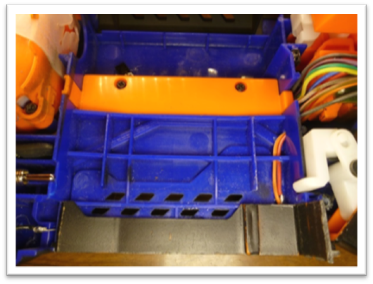
BATTERY TRAY & BATTERY MONITOR
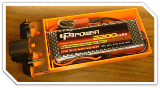
This pin idea worked so well for wiring from one side of the blaster to the other that I decided to use it for the battery tray too. The pins on the back are used to monitor each cell of the batter, as well as (eventually) turn on and off the flashlight mounted in the front.
FUTURE PLANS
This blaster has been so fun to work on, and I just don’t want the fun to stop. But my wife and wallet are complaining. I do hope to incorporate the following in future designs though.
BLUETOOTH: A smartphone controlled Nerf Blaster! Just imagine the possibilities. Remote controlled firing for starting an ambush triggered by motion detected on your smartphone’s camera! Turn the flashlight on/off remotely. Loan your gun to your friend, and then turn on the safety! (evil laugh!)
The Arduino lends itself to Bluetooth rather well. However it will require tons more programming to make the blaster compatible to outside commands and then! THEN! I’ll have to learn how to make apps for smartphones… This could be a ways away.
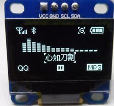
OLED SCREEN: I have already ordered a 128x64 monochrome OLED and I intend to replace the blue 7-segment displays with it. Then I can show what mode the gun is it, what size mag is inserted, how much ammo is remaining, better notification to jams. Plus possible diagnostics and tuning. Maybe a personal score keeper system??
LASER: Lasers are nice because you can shoot from the hip and still aim. Plus they just look cool!
STROBE FLASHLIGHT: Once I finally get the front flashlight working, I will definitely be able to add a strobe mode. I could even time it to flash just after a dart exit barrel.
JAM CONTROL: I am also hoping to install another infrared sensor just after the flywheels so the microcontroller can tell if the dart actually made it out of the blaster.
I am open to new ideas. Either features you’d like to see, or improvements for what it is now. Please post them!
For those of you who read through the whole thing, I applaud you. I’m long winded, but I hope you found it entertaining and informative. Perhaps too informative…
Thank you all!
- Gimmick
Edited by Technician Gimmick, 11 July 2014 - 07:41 PM.


